I want to use an EC1 rotary encoder to control a battery powered device. The EC1 sports a momentary switch, rather than an on / off switch, however, so I need to add a circuit to latch the momentary pulse. Figure 3 on this page should work: http://www.mosaic-industries.com/embedded-systems/microcontroller-projects/electronic-circuits/push-button-switch-turn-on/latching-toggle-power-switch.
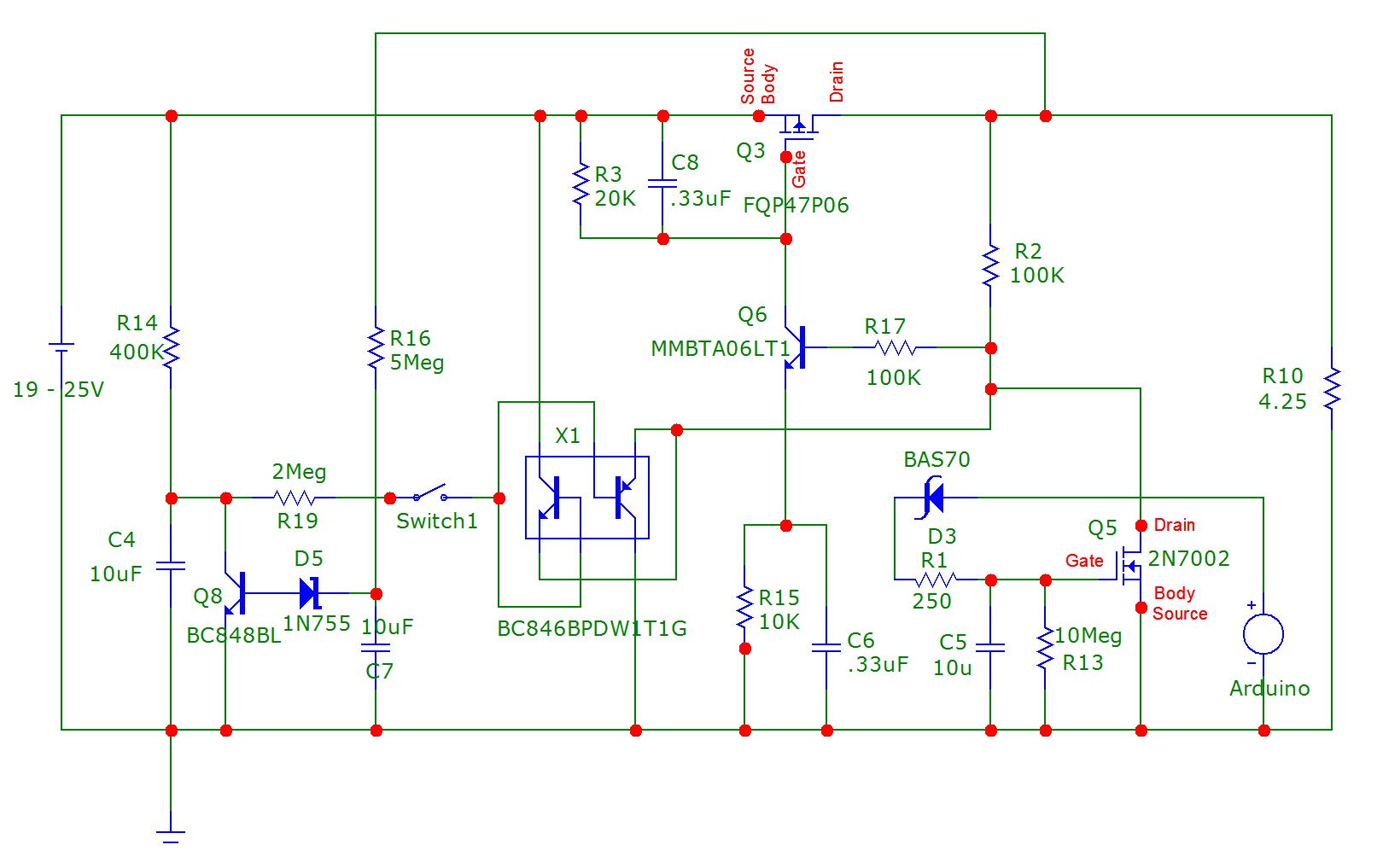
The battery will have an output boltage between 17V and 25V, and the device can use up to 10 amperes, however, so the IRF3719 dual MOSFET suggested on that page won't quite work. Instead, I am using an FQP47P06 P-channel power MOSFET as the mainswitch and a 2N7002 N-channel MOSFET as the gate driver for the FQP47P06. I don't know why, but it isn't working, however. When the button is pushed, if the device is off, the switch properly turns on, but when the device is already on, pushing the
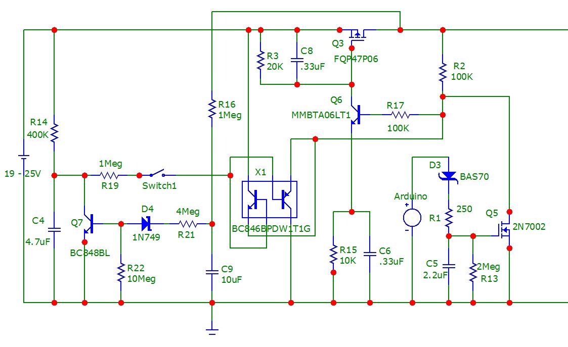
Looking at the scope, it takes about 150 - 200 ms for the voltage to reach this value, which also seems about right, and as expected, it takes considerably longer for the voltage at the 1uF capacitor to recover to near 0V. I am surmising the 19.9 Vlevel experienced at the top of the cap is not high enough to shut off the FQP47P06. I wonder if the modification below would help?
http://siliconventures.net/images/Flashlight%20Switch%20Update.PNG
On Sunday, January 28, 2024 at 12:21:11?PM UTC-6, John Larkin wrote:
On Sun, 28 Jan 2024 09:14:20 -0800 (PST), Les wrote:
http://siliconventures.net/images/Flashlight%20Switch%20Update.PNGThe circuit image is cropped but looks wrong. Spice it.
That is the drawing from the sim. The two lines off to the right go to other parts of the circuit that do not affect the switch.
What looks wrong?
On Sun, 28 Jan 2024 18:09:13 -0800 (PST), "rhor...@gmail.com" ><rhorerles@gmail.com> wrote:
On Sunday, January 28, 2024 at 12:21:11?PM UTC-6, John Larkin wrote:
On Sun, 28 Jan 2024 09:14:20 -0800 (PST), Les wrote:
http://siliconventures.net/images/Flashlight%20Switch%20Update.PNGThe circuit image is cropped but looks wrong. Spice it.
That is the drawing from the sim. The two lines off to the right go to other parts of the circuit that do not affect the switch.
What looks wrong?
As you noted, it doesn't turn off.
The voltage charging C4 is somewhere between 25 and 12.5. It can't
turn off Q2.
On Sunday, January 28, 2024 at 9:09:26?PM UTC-6, John Larkin wrote:
On Sun, 28 Jan 2024 18:09:13 -0800 (PST), Les wrote:Yeah, it seemed... wrong somehow. So much for trusting the internet as a source.
On Sunday, January 28, 2024 at 12:21:11?PM UTC-6, John Larkin wrote:As you noted, it doesn't turn off.
On Sun, 28 Jan 2024 09:14:20 -0800 (PST), Les wrote:
http://siliconventures.net/images/Flashlight%20Switch%20Update.PNGThe circuit image is cropped but looks wrong. Spice it.
That is the drawing from the sim. The two lines off to the right go to other parts of the circuit that do not affect the switch.
What looks wrong?
The voltage charging C4 is somewhere between 25 and 12.5. It can't
turn off Q2.
On Wednesday, February 7, 2024 at 1:04:11 AM UTC-8, rhor...@gmail.c=
om wrote:
Um, yeah, an On / Off switch is a pretty ubiquitous sort of control. Inde= >ed, almost all implementations of switched rotary encoders employ the integ= >rated switch in that way, the fact the encoders have momentary switches not= >withstanding.
The design below seems to work pretty well, at least in the simulator. Do=you know of something better / simpler? Do you have any ideas for improvem=
ent?
http://siliconventures.net/images/Flashlight%20Switch%20Circuit.PNG
Whoa, that's a lot. Couldn't you use something more HV-suitable as a swit= >ch, like
an SCR? Two transistors and it has momentary-ON solved, and if you crowba= >r the
SCR it turns off (yet another momentary switch can do that).
To make a latch-like device, you can do the Eccles-Jordan thing with
two identical transconductors cross-coupled, or the Schmitt trigger with em= >itter coupling, or
the SCR with one NPN and one PNP.
To momentary switch, the SCR is really quite convenient, uses the load cur= >rent to keep it
active instead of steady power-supply drain.
On Tuesday, January 30, 2024 at 7:15:11 AM UTC-6, Anthony William Sloman wrote:contact for less than about 50 ms. It should be obvious that anyone who is not an idiot would experiment with closure times, and I am not an idiot. In the simulator, I emulated button closures as short as 1ms and as long as 10 seconds. The design to
This is much too late to be useful, but you do need to work exactly what you are trying to. The first thing that worries me is that you don't spell out how long the momentary switch closes the contact.At first blush, one might be inclined to ask, "How long does a finger press any button?" I think I know what you mean, however. Certainly most people pressing a button won't typically be able to reliably close a momentary switch and keep that
light power and intensity is a bit strange.You then go on to say you want the same momentary switch to turn off the lamp if you press it when the lamp is on.
Um, yeah, an On / Off switch is a pretty ubiquitous sort of control. Indeed, almost all implementations of switched rotary encoders employ the integrated switch in that way, the fact the encoders have momentary switches notwithstanding.
Life gets a lot simpler if you set up micropower latch to switch between two states - lamp on and lamp off.
I am not entirely sure what you mean, here. I could use a separate SPST switch to power up the device, but that would use up more real estate on the back of the device, and real estate is quite limited. Not only that, but two separate controls for
can be pretty straightforward.It's output can drive the transistor ( the FQP47P06 P-channel power MOSFET). If you have separate logic to treat an output from the momenetary contact as a latch toggling input - directing it to at the Set or Reset inputs to an RS latch - the design
Yes, but this only works if the logic is energized when the device is shut down, or if the logic can be waked up with the momentary switch. The latter is what I have chosen to design using discrete components.
You can buy a CMOS S/R latch, but even 4000 series CMOS has a maximum voltage rating of 18V.
Precisely. I might be able to beat the quiescent current draw using a clever power supply scheme and micropower logic, but this design uses less than 65 microamps, and that is pretty good, I think.
It isn't going to be as cheap or as simple as what you've tried, but it is designable.
The design below seems to work pretty well, at least in the simulator. Do you know of something better / simpler? Do you have any ideas for improvement?
http://siliconventures.net/images/Flashlight%20Switch%20Circuit.PNG
On Sun, 28 Jan 2024 09:14:20 -0800 (PST), "rhor...@gmail.com"www.mosaic-industries.com/embedded-systems/microcontroller-projects/electronic-circuits/push-button-switch-turn-on/latching-toggle-power-switch.
<rhorerles@gmail.com> wrote:
I want to use an EC1 rotary encoder to control a battery powered device. The EC1 sports a momentary switch, rather than an on / off switch, however, so I need to add a circuit to latch the momentary pulse. Figure 3 on this page should work: http://
switch and a 2N7002 N-channel MOSFET as the gate driver for the FQP47P06. I don't know why, but it isn't working, however. When the button is pushed, if the device is off, the switch properly turns on, but when the device is already on, pushing the
The battery will have an output boltage between 17V and 25V, and the device can use up to 10 amperes, however, so the IRF3719 dual MOSFET suggested on that page won't quite work. Instead, I am using an FQP47P06 P-channel power MOSFET as the main
level experienced at the top of the cap is not high enough to shut off the FQP47P06. I wonder if the modification below would help?
Looking at the scope, it takes about 150 - 200 ms for the voltage to reach this value, which also seems about right, and as expected, it takes considerably longer for the voltage at the 1uF capacitor to recover to near 0V. I am surmising the 19.9 V
http://siliconventures.net/images/Flashlight%20Switch%20Update.PNG
The circuit image is cropped but looks wrong. Spice it.
It technically violates the abs-max gate voltage spec of the 2N7002,
but it would probably survive.
I recently bought a bunch of LED flashlights from Amazon. Machined and anodized, adjustable focus, single AA battery, three blink/intensity
modes, really interesting light pattern. $3 each. How can they do
that?
Perhaps they buy them on Aliexpress for $2 https://www.aliexpress.com/item/33020731608.html
Or to answer the implied question, the manufacturers are not buying
their parts from Digikey.
Stick a 14500 lithium-ion cell in there instead of the AA for increased brightness. These are great for reading laser marking on ICs, also inspecting drywall for flatness etc.
On 2024-03-03 09:16, Jasen Betts wrote:
Perhaps they buy them on Aliexpress for $2
https://www.aliexpress.com/item/33020731608.html
Or to answer the implied question, the manufacturers are not buying
their parts from Digikey.
Stick a 14500 lithium-ion cell in there instead of the AA for increased
brightness. These are great for reading laser marking on ICs, also
inspecting drywall for flatness etc.
I like this part of the ad: Emitting Color: black
Arie
| Sysop: | Keyop |
|---|---|
| Location: | Huddersfield, West Yorkshire, UK |
| Users: | 300 |
| Nodes: | 16 (2 / 14) |
| Uptime: | 95:58:45 |
| Calls: | 6,719 |
| Calls today: | 3 |
| Files: | 12,252 |
| Messages: | 5,359,380 |
| Posted today: | 1 |