May seem a daft question, but in the old days of tubes, there were various patterns of shadow masks on them. Some tended to be noticeable as vertical stripes, others as little triads, And when we started to get digital video
as in games, it was not unusual to see oval circles on things, due to the pixel being displayed oblong instead of square, so to speak.
Brian
--
This newsgroup posting comes to you directly from...
The Sofa of Brian Gaff...
bri...@blueyonder.co.uk
Blind user, so no pictures please
Note this Signature is meaningless.!
On Saturday, 19 March 2022 at 10:45:02 UTC, Brian Gaff (Sofa) wrote:
May seem a daft question, but in the old days of tubes, there were
various
patterns of shadow masks on them. Some tended to be noticeable as
vertical
stripes, others as little triads, And when we started to get digital
video
as in games, it was not unusual to see oval circles on things, due to the
pixel being displayed oblong instead of square, so to speak.
Brian
--
This newsgroup posting comes to you directly from...
The Sofa of Brian Gaff...
bri...@blueyonder.co.uk
Blind user, so no pictures please
Note this Signature is meaningless.!
Old CRT's - dots illuminated by electron beam through a shadow mask
Trinitron - lines illuminated by electron beam through wires
Plasma - dots illuminated by plasma from "points" behind"
Most LCD - rectangular, sometimes with extra colours (e.g. Sharp), usually arrayed, but on vertical alignment models they are vertical bars. Great picture, although slow response (so not for gamers)
OLED - dunno, but probably an array.
Micro LED - little LED chips usually arrayed.
On 4k monitors or TV's at a sensible distance it is quite hard to make out the pixels.
RGB and white, presumably the LEDs themselves.
OLED - dunno, but probably an array.
RGB and white, presumably the LEDs themselves.
LEDs can't be white. What are called "white LEDs" are blue LEDs with a >yellow phosphor. They generate a relatively narrow band blue, from the
LED, and a very broadband yellow, from the phosphor. Unpowered I'd
expect "white" LEDs to look yellow.
On Mon, 21 Mar 2022 14:31:29 +0000 (UTC), ric...@cogsci.ed.ac.uk
(Richard Tobin) wrote:
In article <t19s9b$3r1$1...@dont-email.me>,
David Woolley <da...@ex.djwhome.demon.invalid> wrote:
RGB and white, presumably the LEDs themselves.
LEDs can't be white. What are called "white LEDs" are blue LEDs with a >>yellow phosphor. They generate a relatively narrow band blue, from the >>LED, and a very broadband yellow, from the phosphor. Unpowered I'd
expect "white" LEDs to look yellow.
Apparently the RGB ones are R, G and B either. They are "white" OLEDs
with filters over them.
https://www.oled-info.com/lgs-wrgb-oled-tv-sub-pixels-captured-macro-photo
I guess WRGB is just the additive equivalent of CMYK.
-- RichardMy TV has vertical strips, all composed of RGB pixels horizontally
arranged. When all three are on it looks white.
--
Dave W
On 21/03/2022 12:24, Richard Tobin wrote:
RGB and white, presumably the LEDs themselves.
LEDs can't be white. What are called "white LEDs" are blue LEDs with a yellow phosphor. They generate a relatively narrow band blue, from the
LED, and a very broadband yellow, from the phosphor. Unpowered I'd expect "white" LEDs to look yellow.
On Mon, 21 Mar 2022 14:31:29 +0000 (UTC), richard@cogsci.ed.ac.uk
(Richard Tobin) wrote:
In article <t19s9b$3r1$1@dont-email.me>,
David Woolley <david@ex.djwhome.demon.invalid> wrote:
RGB and white, presumably the LEDs themselves.
LEDs can't be white. What are called "white LEDs" are blue LEDs with a >>>yellow phosphor. They generate a relatively narrow band blue, from the >>>LED, and a very broadband yellow, from the phosphor. Unpowered I'd >>>expect "white" LEDs to look yellow.
Apparently the RGB ones are R, G and B either. They are "white" OLEDs
with filters over them.
https://www.oled-info.com/lgs-wrgb-oled-tv-sub-pixels-captured-macro-photo
I guess WRGB is just the additive equivalent of CMYK.
-- Richard
My TV has vertical strips, all composed of RGB pixels horizontally
arranged. When all three are on it looks white.
--
Dave W
I do remember its all to do with colour temperature and lumins, something
I never bothered about when I could see. All I remember was early LEDs
that looked white to the naked eye seemed to look bluish when they were
used daylight around and that most fluorescent tubes looked dotty or
yellow. If you shot pictures with a video in such environments, the latter turned everyone's faces green unless you changed the tint on the camera,
and the former looked a bit like blue light shown through mud is the best
way I can describe it. It does show up how clever the eye and brain are
when they work correctly to getting the colours to look right, wheas electronic devices show what is really there.
I remember taking non flash photos under those orange street lights with
some very alien looking results. Some cars almost shone, yet others were really black even when blue.
Some headlights were greeny yellow,while others were just whitish.
"Brian Gaff (Sofa)" <bri...@blueyonder.co.uk> wrote in message news:t1bvk0$l4s$1...@dont-email.me...
I do remember its all to do with colour temperature and lumins, somethingAny lights with discontinuous spectrums (as opposed to "black body radiation", as taught in physics A level) will appear differently depending on the ways the RGB sensors respond to light.
I never bothered about when I could see. All I remember was early LEDs
that looked white to the naked eye seemed to look bluish when they were used daylight around and that most fluorescent tubes looked dotty or yellow. If you shot pictures with a video in such environments, the latter turned everyone's faces green unless you changed the tint on the camera, and the former looked a bit like blue light shown through mud is the best way I can describe it. It does show up how clever the eye and brain are when they work correctly to getting the colours to look right, wheas electronic devices show what is really there.
I remember taking non flash photos under those orange street lights with some very alien looking results. Some cars almost shone, yet others were really black even when blue.
Some headlights were greeny yellow,while others were just whitish.
I found that, to the naked eye, "daylight white" CFL bulbs looked
beautifully white and matched daylight coming in through windows. But some digital cameras rendered them as very yellow - almost as much as tungsten bulbs - whereas the same camera, with fixed 5000 K "sunlight" white balance, rendered "warm white" fluorescent tubes as being less yellow and more blue even though to the eye they looked warm compared with sunlight.
Most colour slide film (Kodachrome, Ektachrome) rendered fluorescent tubes (probably warm white) as a horrible sickly green which the naked eye could not detect. You could get filters for various types of film which corrected for this.
I found that digital cameras with auto white balance correction, where you point the camera at something white and tell it "this is white", give pretty good rendition of colours in a variety of light sources. The main difference with CFLs and LEDs, compared with tungsten and sun/shade daylight, is that certain shades of red look too dark even though the overall colour balance
is correct.
https://i.postimg.cc/c4TW1zT4/daylight.jpg https://i.postimg.cc/HLrdhtwW/daylight-CFL.jpg https://i.postimg.cc/NfQYct6z/Led.jpg https://i.postimg.cc/1RGP2XqF/white-fluor.jpg https://i.postimg.cc/br9htVhg/white-fluor-daylight-WB.jpg
Are a series of photos of the front cover of an edition of the Radio Times, with a pack of screw that have a saturated red label and a pack of drill
bits that have a royal blue case - so there's a good range of tones. I illuminated it by various light sources, as described in the filename. and auto-white-balanced the camera from light reflected off a sheet of A4
printer paper, lit with the same light source - apart from one case where I used a warm-white fluorescent tube and deliberately set the camera to sunlight WB.
I realise that Brian can't see this. The general colour balance and colour cast for daylight, daylight CFL, LED and (warm) white fluorescent is pretty consistent, though the red panel on the box of screws is much brighter on daylight than on any of the artificial sources. The fluorescent with the camera set for daylight has a pale yellow tint, though nowhere near as the very strong reddish yellow that you'd get with a tungsten bulb.
One of the things you need to be careful of with LEDs is that they are
pulsed at high frequency with a mark:space ratio which varies as you dim the light. This can lead to horizontal bands on photos if the camera sensor
reads the brightness of each row of pixels in turn, and the LEDs were on for some rows and off for others. I presume when LEDs are used to illuminate a
TV studio they are driven from DC, with control over the current to dim the light, so they do not turn on and off.
"Brian Gaff (Sofa)" <briang1@blueyonder.co.uk> wrote in message news:t1bvk0$l4s$1@dont-email.me...
I do remember its all� to do with colour temperature and lumins,
something I never bothered about when I could see. All I remember was
early LEDs that looked white to the naked eye seemed to look bluish
when they were used daylight around and that most fluorescent tubes
looked dotty or yellow. If you shot pictures with a video in such
environments, the latter turned everyone's faces green unless you
changed the tint on the camera, and the former looked a bit like blue
light shown through mud is the best way I can describe it. It does
show up how clever the eye and brain are when they work correctly to
getting the colours to look right, wheas electronic devices show what
is really there.
I remember taking non flash photos under those orange street lights
with some very alien looking results. Some cars almost shone, yet
others were really black even when blue.
Some headlights were greeny yellow,while others were just whitish.
Any lights with discontinuous spectrums (as opposed to "black body radiation", as taught in physics A level) will appear differently
depending on the ways the RGB sensors respond to light.
[snip]
I found that digital cameras with auto white balance correction, where
you point the camera at something white and tell it "this is white",
give pretty good rendition of colours in a variety of light sources. The
main difference with CFLs and LEDs, compared with tungsten and sun/shade daylight, is that certain shades of red look too dark even though the
overall colour balance is correct.
https://i.postimg.cc/c4TW1zT4/daylight.jpg https://i.postimg.cc/HLrdhtwW/daylight-CFL.jpg https://i.postimg.cc/NfQYct6z/Led.jpg https://i.postimg.cc/1RGP2XqF/white-fluor.jpg https://i.postimg.cc/br9htVhg/white-fluor-daylight-WB.jpg
One of the things you need to be careful of with LEDs is that they are
pulsed at high frequency with a mark:space ratio which varies as you dim
the light. This can lead to horizontal bands on photos if the camera
sensor reads the brightness of each row of pixels in turn, and the LEDs
were on for some rows and off for others. I presume when LEDs are used
to illuminate a TV studio they are driven from DC, with control over the current to dim the light, so they do not turn on and off.
On 22/03/2022 09:52, NY wrote:
"Brian Gaff (Sofa)" <briang1@blueyonder.co.uk> wrote in message
news:t1bvk0$l4s$1@dont-email.me...
I do remember its all to do with colour temperature and lumins,
something I never bothered about when I could see. All I remember was
early LEDs that looked white to the naked eye seemed to look bluish when >>> they were used daylight around and that most fluorescent tubes looked
dotty or yellow. If you shot pictures with a video in such environments, >>> the latter turned everyone's faces green unless you changed the tint on
the camera, and the former looked a bit like blue light shown through
mud is the best way I can describe it. It does show up how clever the
eye and brain are when they work correctly to getting the colours to
look right, wheas electronic devices show what is really there.
I remember taking non flash photos under those orange street lights with >>> some very alien looking results. Some cars almost shone, yet others were >>> really black even when blue.
Some headlights were greeny yellow,while others were just whitish.
Any lights with discontinuous spectrums (as opposed to "black body
radiation", as taught in physics A level) will appear differently
depending on the ways the RGB sensors respond to light.
Yes, while the sodium street lights that Brian refers to are predominantly yellow, because the spectrum of sodium has a pair of very bright yellow lines, in fact there are other colours in there as well - although it's
long time since I looked at the spectrum of one of those lamps as part of
a lab experiment, I remember some fainter red and green lines as well. [Searches] Yes, lovely photo of the spectrum here, though I'm not sure
why the areas between the radiation lines aren't black as they were in the experiment that I ran:
https://i.postimg.cc/c4TW1zT4/daylight.jpg
https://i.postimg.cc/HLrdhtwW/daylight-CFL.jpg
https://i.postimg.cc/NfQYct6z/Led.jpg
https://i.postimg.cc/1RGP2XqF/white-fluor.jpg
https://i.postimg.cc/br9htVhg/white-fluor-daylight-WB.jpg
Interesting. Only the last of those looks truly awful. However, can I
offer some advice? Next time use a tripod to ensure that the setup of
each shot is identical. As you suggest most photo/scanning equipment uses correction technologies of some sort, even if it's only as unsophisticated
as 'integrate to grey' in a film-era photo lab's printing machine, and therefore, theoretically at least, varying the composition might alter any auto-corrections applied by the equipment used, and hence the result not
be a comparison only of the light source used, though I admit that such is not apparent in the shots you have linked.
One of the things you need to be careful of with LEDs is that they are
pulsed at high frequency with a mark:space ratio which varies as you dim
the light. This can lead to horizontal bands on photos if the camera
sensor reads the brightness of each row of pixels in turn, and the LEDs
were on for some rows and off for others. I presume when LEDs are used to
illuminate a TV studio they are driven from DC, with control over the
current to dim the light, so they do not turn on and off.
You get similar, but much worse, problems trying to photograph CRT TVs, as
I found when drawing up the following web-pages on my site. Although I haven't illustrated it there, most of the photos of the CRT taken in preparation had to be junked because sections of the picture were very
dark and others very bright - it was rare that by luck the camera
captured one complete CRT scan acceptably evenly. Their primary purpose
was to compare the output of a CRT TV and a flat panel TV displaying the
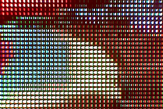
same static picture, but wrt to the current thread title, by chance the second page of the demo shows quite well the effect of the vertical shadow-mask of the CRT, and the actual LEDs of the flat panel.
www.macfh.co.uk/JavaJive/AudioVisualTV/CRTvsLCD/CRTvsLCD-p1.html
What you haven't really mentioned, in fact I don't think anyone really has
in the thread, is the response of the human eye. Although on this subject
I have found contrary information on some sites that I would normally consider to be reliable, my understanding remains as follows.
There are two types of photo-receptive cell in the human eye, rods and
cones (there is actually a third type responsive to photo-period, which is not relevant here), with the former being sensitive to blue light and the latter being further split into two more types being sensitive to red and green light respectively; evolutionarily speaking, the differentiation between red and green came last. The above explains why we are able to
mimic so much of the world that we see by using three primary colours, the additive primaries above, or their corresponding subtractive primaries
yellow (white without blue), magenta (ditto green), and cyan (ditto red).
A point often overlooked is that the cones are less sensitive than the
rods, hence, as dusk falls, our seeing of red and green starts to fail
before our seeing of blue, resulting in what the French expressively call "L'Heure Bleu", "The Blue Hour", around dusk. However, this also affects
the colours we see under sodium street lighting, because of the faintness
of the other colours in sodium's spectrum.
You should be able to demonstrate this relative sensitivity to yourselves with the following picture. Print it out and leave it on a window sill
where there is no artificial light as dusk begins to fall. You should
observe that to begin with the red and perhaps the green appear brighter
than the blue, but as the daylight fades there'll come a point where the
blue should appear brighter than the other two colours. At this point, the cones are failing, but the rods are still working.
www.macfh.co.uk/Temp/RedGreenBlue.png
For completeness, there is also a subtractive primary version of the
above, but I don't recall ever trying to see what happens to this as dusk falls!
www.macfh.co.uk/Temp/CyanMagentaYellow.png
https://i.postimg.cc/c4TW1zT4/daylight.jpg https://i.postimg.cc/HLrdhtwW/daylight-CFL.jpg https://i.postimg.cc/NfQYct6z/Led.jpg https://i.postimg.cc/1RGP2XqF/white-fluor.jpg https://i.postimg.cc/br9htVhg/white-fluor-daylight-WB.jpg
The best way to photograph a TV screen apparently is to use a small aperture >and/or a neutral density filter to make the exposure several seconds, so the >difference between n and n+1 scans in different parts of the frame is
minimal because n is large.
On 22/03/2022 09:52, NY wrote:
https://i.postimg.cc/c4TW1zT4/daylight.jpg
https://i.postimg.cc/HLrdhtwW/daylight-CFL.jpg
https://i.postimg.cc/NfQYct6z/Led.jpg
https://i.postimg.cc/1RGP2XqF/white-fluor.jpg
https://i.postimg.cc/br9htVhg/white-fluor-daylight-WB.jpg
You should have equalised the exposures and gamma in order to make a >comparison.
Bill
On Tue, 22 Mar 2022 18:38:11 -0000, "NY" <me@privacy.invalid> wrote:
The best way to photograph a TV screen apparently is to use a small >aperture and/or a neutral density filter to make the exposure several >seconds, so the difference between n and n+1 scans in different parts
of the frame is minimal because n is large.
Once I worked in a university audiovisual department, where we would occasionally be asked - sometimes by professors or other clever people
with letters after their names - if when photographing a TV screen it
was best to have the camera's flash switched on or off.
Apparently it's possible to live in the real world but not pay much
attention to it.
Rod.
Back in the 1970s, I was showing off Ceefax at the TV exhibition in Montreaux. Someone wanted a picture of the screen, held up his light meter, remarked that it was quite low levle, so turned on his flash. I wonder
what he though when thefilm came back from the lab.
On Wed, 23 Mar 2022 02:44:31 +0000, williamwright
<wrightsaerials@f2s.com> wrote:
On 22/03/2022 09:52, NY wrote:
https://i.postimg.cc/c4TW1zT4/daylight.jpg
https://i.postimg.cc/HLrdhtwW/daylight-CFL.jpg
https://i.postimg.cc/NfQYct6z/Led.jpg
https://i.postimg.cc/1RGP2XqF/white-fluor.jpg
https://i.postimg.cc/br9htVhg/white-fluor-daylight-WB.jpg
You should have equalised the exposures and gamma in order to make a >>comparison.
Bill
Maybe also use a variety of natural test subjects covering the full
visible spectrum. A photograph in a printed magazine has already been analysed by a filter system and then displayed using only three
artificial pigments.
"Java Jive" <java@evij.com.invalid> wrote in message news:t1cmph$u4e$1@dont-email.me...
Yes, while the sodium street lights that Brian refers to are
predominantly yellow, because the spectrum of sodium has a pair of
very bright yellow lines, in fact there are other colours in there as
well� - although it's long time since I looked at the spectrum of one
of those lamps as part of a lab experiment, I remember some fainter
red and green lines as well. [Searches]� Yes, lovely photo of the
spectrum here, though I'm not sure why the areas between the radiation
lines aren't black as they were in the experiment that I ran:
www.macfh.co.uk/JavaJive/AudioVisualTV/CRTvsLCD/CRTvsLCD-p1.html
Also there are two types of sodium lights. Low pressure ones are the
sort that were used for street lights and were truly horrible as a light source because they are virtually monochromatic and so don't give any perception of colour. But there are also high-pressure ones which give a peach-coloured light with a bit of colour perception because they have a broader spectrum - ie a greater spread of discrete lines.
https://i.postimg.cc/c4TW1zT4/daylight.jpg
https://i.postimg.cc/HLrdhtwW/daylight-CFL.jpg
https://i.postimg.cc/NfQYct6z/Led.jpg
https://i.postimg.cc/1RGP2XqF/white-fluor.jpg
https://i.postimg.cc/br9htVhg/white-fluor-daylight-WB.jpg
Interesting.� Only the last of those looks truly awful.� However, can
I offer some advice?� Next time use a tripod to ensure that the setup
of each shot is identical.� As you suggest most photo/scanning
equipment uses correction technologies of some sort, even if it's only
as unsophisticated as 'integrate to grey' in a film-era photo lab's
printing machine, and therefore, theoretically at least, varying the
composition might alter any auto-corrections applied by the equipment
used, and hence the result not be a comparison only of the light
source used, though I admit that such is not apparent in the shots you
have linked.
I had to take the photos in a variety of locations, depending on where
there was a lamp of the desired type. In all cases I white-balanced off
a piece of paper which completely filled the frame, so the camera would
only "see" white of the appropriate colour. There may be slight
differences in exposure, though I tried to make sure the test image
filled almost the whole frame. I should have stuck the loose objects
(box of screws and box of drills) to the background image so they were
in identical locations for all shots and ensured all the images were
framed identically.
One of the things you need to be careful of with LEDs is that they
are pulsed at high frequency with a mark:space ratio which varies as
you dim the light. This can lead to horizontal bands on photos if the
camera sensor reads the brightness of each row of pixels in turn, and
the LEDs were on for some rows and off for others. I presume when
LEDs are used to illuminate a TV studio they are driven from DC, with
control over the current to dim the light, so they do not turn on and
off.
You get similar, but much worse, problems trying to photograph CRT
TVs, as I found when drawing up the following web-pages on my site.
Although I haven't illustrated it there, most of the photos of the CRT
taken in preparation had to be junked because sections of the picture
were very dark and others very bright� -� it was rare that by luck the
camera captured one complete CRT scan acceptably evenly.� Their
primary purpose was to compare the output of a CRT TV and a flat panel
TV displaying the same static picture, but wrt to the current thread
title, by chance the second page of the demo shows quite well the
effect of the vertical shadow-mask of the CRT, and the actual LEDs of
the flat panel.
The best way to photograph a TV screen apparently is to use a small
aperture and/or a neutral density filter to make the exposure several seconds, so the difference between n and n+1 scans in different parts of
the frame is minimal because n is large. Obviously this only works with
a still image on the TV screen ;-)� ND filter is probably a better way because most lenses have an optimum aperture: too large (small f number)
and parts of the screen may be out of focus when the centre is in focus,
but too small an aperture may introduce diffraction effects.
www.macfh.co.uk/JavaJive/AudioVisualTV/CRTvsLCD/CRTvsLCD-p1.html
An interesting comparison.
The other problem that you might encounter is moir�: a wavy-line pattern which is "beating" between the pixel spacing in the source image and
that in the photo of the screen, though perhaps it is less so when the
pixels of the source image are so much larger than the pixels of your
photos of the screen.
It would be interesting to compare those photos with the original image,
if you can grab it electronically and scale it the same as the photos of
the screen.
What you haven't really mentioned, in fact I don't think anyone really
has in the thread, is the response of the human eye.� Although on this
subject I have found contrary information on some sites that I would
normally consider to be reliable, my understanding remains as follows.
There are two types of photo-receptive cell in the human eye, rods and
cones (there is actually a third type responsive to photo-period,
which is not relevant here), with the former being sensitive to blue
light and the latter being further split into two more types being
sensitive to red and green light respectively; evolutionarily
speaking, the differentiation between red and green came last.� The
above explains why we are able to mimic so much of the world that we
see by using three primary colours, the additive primaries above, or
their corresponding subtractive primaries yellow (white without blue),
magenta (ditto green), and cyan (ditto red).
A point often overlooked is that the cones are less sensitive than the
rods, hence, as dusk falls, our seeing of red and green starts to fail
before our seeing of blue, resulting in what the French expressively
call "L'Heure Bleu", "The Blue Hour", around dusk.� However, this also
affects the colours we see under sodium street lighting, because of
the faintness of the other colours in sodium's spectrum.
You should be able to demonstrate this relative sensitivity to
yourselves with the following picture.� Print it out and leave it on a
window sill where there is no artificial light as dusk begins to fall.
You should observe that to begin with the red and perhaps the green
appear brighter than the blue, but as the daylight fades there'll come
a point where the blue should appear brighter than the other two
colours. At this point, the cones are failing, but the rods are still
working.
www.macfh.co.uk/Temp/RedGreenBlue.png
For completeness, there is also a subtractive primary version of the
above, but I don't recall ever trying to see what happens to this as
dusk falls!
www.macfh.co.uk/Temp/CyanMagentaYellow.png
Amazing what facts the brain retains without you knowing. As soon as I
read your description, the term "Purkinje effect" spring into my brain.
I didn't know that I knew about this...
On 23/03/2022 10:17, charles wrote:
Back in the 1970s, I was showing off Ceefax at the TV exhibition in
Montreaux. Someone wanted a picture of the screen, held up his light
meter,
remarked that it was quite low levle, so turned on his flash. I wonder
what he though when thefilm came back from the lab.
He'd think the telly was faulty.
On Tue, 22 Mar 2022 18:38:11 -0000, "NY" <me@privacy.invalid> wrote:
The best way to photograph a TV screen apparently is to use a small aperture >> and/or a neutral density filter to make the exposure several seconds, so the >> difference between n and n+1 scans in different parts of the frame is
minimal because n is large.
Once I worked in a university audiovisual department, where we would occasionally be asked - sometimes by professors or other clever people
with letters after their names - if when photographing a TV screen it
was best to have the camera's flash switched on or off.
Apparently it's possible to live in the real world but not pay much
attention to it.
The other problem that you might encounter is moir�: a wavy-line pattern
which is "beating" between the pixel spacing in the source image and that
in the photo of the screen, though perhaps it is less so when the pixels
of the source image are so much larger than the pixels of your photos of
the screen.
Yes, I've seen that often, particularly in JPGs, and also in scans of 120 film negatives that were too big to fit in the neg holder of my scanner,
so had to be laid flat on the glass, and actually weren't quite completely flat, resulting in what I call Moir�, others call Newton's rings. I still have about 20-30 of these latter that gave this problem, even under glass, and that I hope to rescan with a better quality result one day.
It's not immediately obvious which displays work by reflection and which
by producing light. LCDs work by reflection, but what if it relies on a backlight? There are shopping coupons which are scanned by a laser in the shop, but, if you don't have access to a printer, you are supposed to be
able to scan the bar/QR code on a smartphone screen; how does that work?
What if the display is OLED?
On 23/03/2022 10:17, charles wrote:
Back in the 1970s, I was showing off Ceefax at the TV exhibition in Montreaux.Crystal Palace had one hell of a range !
Back in the 1970s, I was showing off Ceefax at the TV exhibition in Montreaux.Crystal Palace had one hell of a range !
In article <ja0ktpFgm4bU1@mid.individual.net>,Ah, very good. Back in those days even almost-rival manufacturers would
Mark Carver <mark.carver@invalid.invalid> wrote:
On 23/03/2022 10:17, charles wrote:no, the signal was coming from a VT on the Ampex stand 2 floors down.
Back in the 1970s, I was showing off Ceefax at the TV exhibition inCrystal Palace had one hell of a range !
Montreaux.
I could get R2 on my car radio (expect under the overhead tram wires.Yep, good old Droitwich normally made it with the radio near the hotel
On 23/03/2022 14:11, charles wrote:
In article <ja0ktpFgm4bU1@mid.individual.net>,Ah, very good. Back in those days even almost-rival manufacturers would happily swap feeds between stands.
Mark Carver <mark.carver@invalid.invalid> wrote:
On 23/03/2022 10:17, charles wrote:no, the signal was coming from a VT on the Ampex stand 2 floors down.
Back in the 1970s, I was showing off Ceefax at the TV exhibition inCrystal Palace had one hell of a range !
Montreaux.
Lots of Hum-Buckers everywhere of course.
SDI took the fun out of that,
but by then the 'grown-ups' had put a stop to those sort of things.
I could get R2 on my car radio (expect under the overhead tram wires.Yep, good old Droitwich normally made it with the radio near the hotel
room window
My scanner tends to produce better results (better tonal range) if I
scan as a positive and correct in software, rather than scan as a (B&W) negative. But negs in general (and especially colour ones) are a lot
more difficult to get good scans from than positive slides.
Thankfully all
the slides I chose seem to have been something over than Kodachrome so
the IR dirt-reduction algorithm worked OK (unlike Agfa and Kodak
Ektachrome, Kodachrome has an emulsion which is not uniformly
transparent to IR, so the algorithm which uses IR to look for dirt and
dust on the film doesn't work because it sees darker parts of the image
as dirt).
"Max Demian" <max_demian@bigfoot.com> wrote in message >news:E82dnS-guvgpl6b_nZ2dnUU7-c3NnZ2d@brightview.co.uk...
It's not immediately obvious which displays work by reflection and which
by producing light. LCDs work by reflection, but what if it relies on a
backlight? There are shopping coupons which are scanned by a laser in the
shop, but, if you don't have access to a printer, you are supposed to be
able to scan the bar/QR code on a smartphone screen; how does that work?
What if the display is OLED?
Like you, I've always wondered how laser barcode scanners manage to scan a >backlit LED screen rather than a reflective paper coupon (or an LCD screen). >Scanners in shops seem to have a switchable setting which maybe turns the >laser off and moves the sensor (or relies on movement of the phone screen >past the scanner) to sense the horizontal axis of the bar code.
Apparently when CRTs were included in vision for a film camera or a TV >camera, the camera was synchronised with the video sync to avoid a rolling >bar on the screen image: maybe even run the camera without film, checking
for a visible bar in the viewfinder and adjusting phase to move it >off-screen.
On Wed, 23 Mar 2022 11:29:54 -0000, "NY" <me@privacy.invalid> wrote:
Apparently when CRTs were included in vision for a film camera or a TV >>camera, the camera was synchronised with the video sync to avoid a rolling >>bar on the screen image: maybe even run the camera without film, checking >>for a visible bar in the viewfinder and adjusting phase to move it >>off-screen.
It's not possible to "overcrank" or "undercrank" a TV camera to a
different frame rate in the same way as a film camera, so it can't
actually be synchronised to anything other than system sync pulses.
Computer CRT scanning rates were unrelated to TV rates and usually
much higher, so electrically synchronising the cameras would have been
out of the question.
It's actually the exposure time of the camera, not synchronisation,
that was adjusted to accommodate in-vision computer CRT displays, and
it only became possible with the advent of solid state "chip" cameras.
The start of the time interval for which the chip was sensitive to
light could be adjusted, sometimes continuously and sometimes in steps depending on the design of the camera, but the readout time at the end
of that interval had to be synchronised to television system pulses.
There would still be randomly positioned horizontal bars on the CRT
display, but with zero overlap, which would be less visible as long as
the camera didn't pan.
It was easy to confirm this by pointing a camera at a television
monitor displaying something bright with the same scanning rate as the camera, while adjusting the electronic shutter control of the camera.
It would be the upper edge of the bright bar, i.e. the start of the
exposure time, that would move as the control was adjusted.
"Max Demian" <max_demian@bigfoot.com> wrote in message news:E82dnS-guvgpl6b_nZ2dnUU7-c3NnZ2d@brightview.co.uk...
It's not immediately obvious which displays work by reflection and
which by producing light. LCDs work by reflection, but what if it
relies on a backlight? There are shopping coupons which are scanned by
a laser in the shop, but, if you don't have access to a printer, you
are supposed to be able to scan the bar/QR code on a smartphone
screen; how does that work? What if the display is OLED?
Like you, I've always wondered how laser barcode scanners manage to scan
a backlit LED screen rather than a reflective paper coupon (or an LCD screen). Scanners in shops seem to have a switchable setting which maybe turns the laser off and moves the sensor (or relies on movement of the
phone screen past the scanner) to sense the horizontal axis of the bar
code.
May seem a daft question, but in the old days of tubes, there were various patterns of shadow masks on them. Some tended to be noticeable as vertical stripes, others as little triads, And when we started to get digital video
as in games, it was not unusual to see oval circles on things, due to the pixel being displayed oblong instead of square, so to speak.
Brian
--
This newsgroup posting comes to you directly from...
The Sofa of Brian Gaff...
bri...@blueyonder.co.uk
Blind user, so no pictures please
Note this Signature is meaningless.!
I would have thought that to be able to use a TV camera to view a TV screen, >you want the shutter speed to be the full 1/25 second, especially if the TV >screen fills the majority for the frame. If the screen fills (for example)
50 lines of the camera, you can use a correspondingly shorter shutter speed >as the camera will only see the TV screen for 50/625 * 1/25 second.
Vertical scan is actually 50Hz not 25, but the principle is the same.
But if interlaced, e.g. standard analogue TV,
On 25/03/2022 10:11, Roderick Stewart wrote:
Vertical scan is actually 50Hz not 25, but the principle is the same.
But if interlaced, e.g. standard analogue TV, the whole picture requires
two vertical scans, one for odd and one for even lines.
On Saturday, 19 March 2022 at 10:45:02 UTC, Brian Gaff (Sofa) wrote:
May seem a daft question, but in the old days of tubes, there were
various
patterns of shadow masks on them. Some tended to be noticeable as
vertical
stripes, others as little triads, And when we started to get digital
video
as in games, it was not unusual to see oval circles on things, due to the
pixel being displayed oblong instead of square, so to speak.
Brian
--
This newsgroup posting comes to you directly from...
The Sofa of Brian Gaff...
bri...@blueyonder.co.uk
Blind user, so no pictures please
Note this Signature is meaningless.!
It seems Samsung has opted for triangular on its new OLED TV's, but: -
https://www.techradar.com/news/samsung-might-have-a-problem-with-its-new-oled-tvs-sub-pixels
"David Woolley" <david@ex.djwhome.demon.invalid> wrote in message >news:t1ld4c$ce2$1@dont-email.me...
On 25/03/2022 10:11, Roderick Stewart wrote:
Vertical scan is actually 50Hz not 25, but the principle is the same.
But if interlaced, e.g. standard analogue TV, the whole picture requires
two vertical scans, one for odd and one for even lines.
I presume that digital tuners and recorders that have an analogue SCART or
RF output for compatibility with analogue TVs will *always* output >interlaced, even if the digital source happens to be 25p (SD or HD), because >analogue signals are *defined* to be interlaced, and 25p would look very >flickery. Obviously in the case of HD, the tuner/PVR also has to downscale >from 1080 to 576 lines.
Back in the 1970s, I was showing off Ceefax at the TV exhibition in
Montreaux.
Crystal Palace had one hell of a range !
no, the signal was coming from a VT on the Ampex stand 2 floors down.
Ah, very good. Back in those days even almost-rival manufacturers would happily swap feeds between stands.
Lots of Hum-Buckers everywhere of course. SDI took the fun out of that,
but by then the 'grown-ups' had put a stop to those sort of things.
I could get R2 on my car radio (expect under the overhead tram wires.
Yep, good old Droitwich normally made it with the radio near the hotel
room window
On Wed, 23 Mar 2022 15:35:52 +0000, Mark CarverOne of my friends have been using autoclicker (the most latest version) and told me that he is having great experience with op auto clicker despite having some sort of mixed opinions about the software. Here is the link https://autoclicker.online/
<mark....@invalid.invalid> wrote:
Back in the 1970s, I was showing off Ceefax at the TV exhibition in
Montreaux.
Crystal Palace had one hell of a range !
no, the signal was coming from a VT on the Ampex stand 2 floors down.
Ah, very good. Back in those days even almost-rival manufacturers would happily swap feeds between stands.
Lots of Hum-Buckers everywhere of course. SDI took the fun out of that,
but by then the 'grown-ups' had put a stop to those sort of things.
I could get R2 on my car radio (expect under the overhead tram wires.
Yep, good old Droitwich normally made it with the radio near the hotelI picked it up (R4 then of course) on higher ground in Majorca on the bog-standard hire car radio, about 25 years ago.
room window
| Sysop: | Keyop |
|---|---|
| Location: | Huddersfield, West Yorkshire, UK |
| Users: | 297 |
| Nodes: | 16 (2 / 14) |
| Uptime: | 10:31:25 |
| Calls: | 6,666 |
| Files: | 12,213 |
| Messages: | 5,336,335 |