Hi
I need a low distributed capacitance winding transformer, for a HV
stepup function (3.5kV)
I am zeroing in on similar concept as CCFL transformers with
sectionalized bobbin.
For example:
https://www.coilcraft.com/en-us/products/transformers/power-transformers/ccfl-transformers/fl/
Possibly using Triple Insulated Wire to create some distance between the >individual turns.
Not many sells CCFLs these days.
Guess I will keep it alive....
Regards
Klaus
On Wed, 24 Apr 2024 01:57:36 +0200, Klaus Vestergaard Kragelund <klauskvik@hotmail.com> wrote:
Hi
I need a low distributed capacitance winding transformer, for a HV
step-up function (3.5kV)
I am zeroing in on similar concept as CCFL transformers with
sectionalized bobbin.
For example:
https://www.coilcraft.com/en-us/products/transformers/power-transformers/ccfl-transformers/fl/
Possibly using Triple Insulated Wire to create some distance between the
individual turns.
Not many sells CCFLs these days.
Guess I will keep it alive....
Can you use a C-W multiplier?
For low current, you can do resonant tricks too.
Hi
I need a low distributed capacitance winding transformer, for a HV
stepup function (3.5kV)
I am zeroing in on similar concept as CCFL transformers with
sectionalized bobbin.
For example:
https://www.coilcraft.com/en-us/products/transformers/power-transformers/ccfl-transformers/fl/
Possibly using Triple Insulated Wire to create some distance between the >individual turns.
Not many sells CCFLs these days.
Guess I will keep it alive....
Regards
Klaus
On Wed, 24 Apr 2024 01:57:36 +0200, Klaus Vestergaard Kragelund ><klauskvik@hotmail.com> wrote:
Hi
I need a low distributed capacitance winding transformer, for a HV
stepup function (3.5kV)
I am zeroing in on similar concept as CCFL transformers with
sectionalized bobbin.
For example:
https://www.coilcraft.com/en-us/products/transformers/power-transformers/ccfl-transformers/fl/
Possibly using Triple Insulated Wire to create some distance between the >>individual turns.
Not many sells CCFLs these days.
Guess I will keep it alive....
Regards
Klaus
When there are a lot of turns, 3xFEP is not the way to
go. Too bulky. The three layers is basically a trick to
avoid creepage requirements for pri-sec safety. That's
not what you need here.
Anything off the shelf will be a great time saver.
RL
On Wed, 24 Apr 2024 01:57:36 +0200, Klaus Vestergaard Kragelund <klauskvik@hotmail.com> wrote:
Hi
I need a low distributed capacitance winding transformer, for a HV
stepup function (3.5kV)
I am zeroing in on similar concept as CCFL transformers with
sectionalized bobbin.
For example:
https://www.coilcraft.com/en-us/products/transformers/power-transformers/ccfl-transformers/fl/
Possibly using Triple Insulated Wire to create some distance between the
individual turns.
Not many sells CCFLs these days.
Guess I will keep it alive....
Regards
Klaus
Can you use a C-W multiplier?
For low current, you can do resonant tricks too.
Hi
I need a low distributed capacitance winding transformer, for a HV
stepup function (3.5kV)
I am zeroing in on similar concept as CCFL transformers with
sectionalized bobbin.
For example:
<https://www.coilcraft.com/en-us/products/transformers/power-transformers/ccfl-transformers/fl/>
Possibly using Triple Insulated Wire to create some distance between the >individual turns.
Not many sell CCFLs these days.
Guess I will keep it alive....
Regards
Klaus
HiI need a low distributed capacitance winding transformer, for a HV stepup function (3.5kV)I am zeroing in on similar concept as CCFL transformers with sectionalized bobbin.For example:https://www.coilcraft.com/en-us/products/transformers/power-transformers/ccfl-transformers/fl/Possibly using Triple Insulated Wire to create some distance between the individual turns.Not many sells CCFLs these days.Guess I will keep it alive....RegardsKlaus
On 24/04/2024 12:25 pm, John Larkin wrote:
On Wed, 24 Apr 2024 01:57:36 +0200, Klaus Vestergaard Kragelund
<klauskvik@hotmail.com> wrote:
Hi
I need a low distributed capacitance winding transformer, for a HV
step-up function (3.5kV)
I am zeroing in on similar concept as CCFL transformers with
sectionalized bobbin.
For example:
https://www.coilcraft.com/en-us/products/transformers/power-transformers/ccfl-transformers/fl/
Possibly using Triple Insulated Wire to create some distance between the >>> individual turns.
Not many sells CCFLs these days.
Guess I will keep it alive....
Can you use a C-W multiplier?
For low current, you can do resonant tricks too.
It's easier to use a voltage doubler or tripler that it is to find a multi-section former off-the shelf. The occasional high voltage power
supply that I've dismantled clearly used proprietary formers, as do the Coilcraft parts
I suppose one could use self-bonding wire to make a series of
self-supporting pancake windings, but I've never heard of anybody doing it.
The Baxandall configuration is definitely a resonant trick, and copes
with the interwinding capacitance by resonating it with the winding inductance.
There's nothing "low current" about it, but if you are working at higher currents and powers you can justify even more elaborate switching arrangements.
http://sophia-elektronica.com/Baxandall1959JM.pdf
Jim Williams talked about it a lot - application notes AN45, AN49, AN51, AN55, AN61, AN65 - but described it as a "a current driven Royer
inverter" which is simply wrong.
MOSFETs work better as switches than bipolar transistors, and don't seem
to "squeg".
On 24/04/2024 12:25 pm, John Larkin wrote:
On Wed, 24 Apr 2024 01:57:36 +0200, Klaus Vestergaard Kragelund
<klauskvik@hotmail.com> wrote:
Hi
I need a low distributed capacitance winding transformer, for a HV
step-up function (3.5kV)
I am zeroing in on similar concept as CCFL transformers with
sectionalized bobbin.
For example:
https://www.coilcraft.com/en-us/products/transformers/power-transformers/ccfl-transformers/fl/
Possibly using Triple Insulated Wire to create some distance between the >>> individual turns.
Not many sells CCFLs these days.
Guess I will keep it alive....
Can you use a C-W multiplier?
For low current, you can do resonant tricks too.
It's easier to use a voltage doubler or tripler that it is to find a multi-section former off-the shelf. The occasional high voltage power
supply that I've dismantled clearly used proprietary formers, as do the Coilcraft parts
I suppose one could use self-bonding wire to make a series of
self-supporting pancake windings, but I've never heard of anybody doing it.
On Wed, 24 Apr 2024 01:57:36 +0200, Klaus Vestergaard Kragelund <klauskvik@hotmail.com> wrote:
Hi
I need a low distributed capacitance winding transformer, for a HV
stepup function (3.5kV)
I am zeroing in on similar concept as CCFL transformers with
sectionalized bobbin.
For example:
https://www.coilcraft.com/en-us/products/transformers/power-transformers/ccfl-transformers/fl/
Possibly using Triple Insulated Wire to create some distance between the
individual turns.
Not many sells CCFLs these days.
Guess I will keep it alive....
Regards
Klaus
When there are a lot of turns, 3xFEP is not the way to
go. Too bulky. The three layers is basically a trick to
avoid creepage requirements for pri-sec safety. That's
not what you need here.
Anything off the shelf will be a great time saver.
On 24/04/2024 3:10 pm, Bill Sloman wrote:
On 24/04/2024 12:25 pm, John Larkin wrote:
On Wed, 24 Apr 2024 01:57:36 +0200, Klaus Vestergaard Kragelund
<klauskvik@hotmail.com> wrote:
Hi
I need a low distributed capacitance winding transformer, for a HV
step-up function (3.5kV)
I am zeroing in on similar concept as CCFL transformers with
sectionalized bobbin.
For example:
https://www.coilcraft.com/en-us/products/transformers/power-transformers/ccfl-transformers/fl/
Possibly using Triple Insulated Wire to create some distance between
the
individual turns.
Not many sells CCFLs these days.
Guess I will keep it alive....
Can you use a C-W multiplier?
For low current, you can do resonant tricks too.
It's easier to use a voltage doubler or tripler that it is to find a
multi-section former off-the shelf. The occasional high voltage power
supply that I've dismantled clearly used proprietary formers, as do
the Coilcraft parts
I suppose one could use self-bonding wire to make a series of
self-supporting pancake windings, but I've never heard of anybody
doing it.
The Baxandall configuration is definitely a resonant trick, and copes
with the interwinding capacitance by resonating it with the winding
inductance.
There's nothing "low current" about it, but if you are working at
higher currents and powers you can justify even more elaborate
switching arrangements.
http://sophia-elektronica.com/Baxandall1959JM.pdf
Jim Williams talked about it a lot - application notes AN45, AN49,
AN51, AN55, AN61, AN65 - but described it as a "a current driven Royer
inverter" which is simply wrong.
MOSFETs work better as switches than bipolar transistors, and don't
seem to "squeg".
The Coilcraft data sheets don't say anything much about the resonant frequencies of their transformers - except "The FL Series of
transformers is designed for use in cold cathode fluorescent lamp (CCFL) power supplies at operating frequencies up to 100 kHz" where the "up to 100kHz" gives them a lot of wriggle room.
A primary inductance of around 50uH with a 100:1 step-up implies a 0.5H secondary inductance. 10pF parallel capacitance would give a 71kHz
resonant frequency, which is less than 100kHz.
Of course once you have one of the Coilcraft parts you can measure the resonant frequency.
On 24-04-2024 07:10, Bill Sloman wrote:
On 24/04/2024 12:25 pm, John Larkin wrote:
On Wed, 24 Apr 2024 01:57:36 +0200, Klaus Vestergaard Kragelund
<klauskvik@hotmail.com> wrote:
Hi
I need a low distributed capacitance winding transformer, for a HV
step-up function (3.5kV)
I am zeroing in on similar concept as CCFL transformers with
sectionalized bobbin.
For example:
https://www.coilcraft.com/en-us/products/transformers/power-transformers/ccfl-transformers/fl/
Possibly using Triple Insulated Wire to create some distance between
the
individual turns.
Not many sells CCFLs these days.
Guess I will keep it alive....
Can you use a C-W multiplier?
For low current, you can do resonant tricks too.
It's easier to use a voltage doubler or tripler that it is to find a
multi-section former off-the shelf. The occasional high voltage power
supply that I've dismantled clearly used proprietary formers, as do
the Coilcraft parts
I am using it for pulse generation, so cannot use a capacitive doubler
I suppose one could use self-bonding wire to make a series ofYeah, sounds like difficult to do in production.
self-supporting pancake windings, but I've never heard of anybody
doing it.
On Wed, 24 Apr 2024 01:57:36 +0200, Klaus Vestergaard Kragelund <klauskvik@hotmail.com> wrote:
Hi
I need a low distributed capacitance winding transformer, for a HV
stepup function (3.5kV)
I am zeroing in on similar concept as CCFL transformers with
sectionalized bobbin.
I'd look into Pi Winding HV transformers.
.<https://www.edn.com/two-pi-winding/>
Lots of construction details from the Radio Amateur community.
On Wed, 24 Apr 2024 09:37:24 -0400, legg <legg@nospam.magma.ca> wrote:
On Wed, 24 Apr 2024 01:57:36 +0200, Klaus Vestergaard Kragelund
<klauskvik@hotmail.com> wrote:
Hi
I need a low distributed capacitance winding transformer, for a HV
stepup function (3.5kV)
I am zeroing in on similar concept as CCFL transformers with
sectionalized bobbin.
For example:
https://www.coilcraft.com/en-us/products/transformers/power-transformers/ccfl-transformers/fl/
Possibly using Triple Insulated Wire to create some distance between the >>> individual turns.
Not many sells CCFLs these days.
Guess I will keep it alive....
Regards
Klaus
When there are a lot of turns, 3xFEP is not the way to
go. Too bulky. The three layers is basically a trick to
avoid creepage requirements for pri-sec safety. That's
not what you need here.
Anything off the shelf will be a great time saver.
RL
I sometimes use an autoflyback stage with a DRQ-series dual inductor, followed by a c-w multiplier using sot-23 dual HV diodes. That's cheap
and easy, given a reasonable supply voltage, like 24.
You can also just buy a potted HV supply and move on to design
something else.
There are also potted c-w bricks, but they are a lot more expensive
than buying the diodes and caps.
Custom magnetics only makes sense at high volume, or for real exotica
like transmission-line transformers.
I'm about to embark on a custom tapped inductor and I'm not looking
forward to it. Drawings, quotes, revised drawings, more quotes,
samples, tests, released drawings, MOQs, all that.
Hi
I need a low distributed capacitance winding transformer, for a HV
stepup function (3.5kV)
I am zeroing in on similar concept as CCFL transformers with
sectionalized bobbin.
For example:
https://www.coilcraft.com/en-us/products/transformers/power-transformers/ccfl-transformers/fl/
Possibly using Triple Insulated Wire to create some distance between the >individual turns.
Not many sells CCFLs these days.
Guess I will keep it alive....
Regards
Klaus
On 24-04-2024 16:23, John Larkin wrote:
On Wed, 24 Apr 2024 09:37:24 -0400, legg <legg@nospam.magma.ca> wrote:
On Wed, 24 Apr 2024 01:57:36 +0200, Klaus Vestergaard Kragelund
<klauskvik@hotmail.com> wrote:
Hi
I need a low distributed capacitance winding transformer, for a HV
stepup function (3.5kV)
I am zeroing in on similar concept as CCFL transformers with
sectionalized bobbin.
For example:
https://www.coilcraft.com/en-us/products/transformers/power-transformers/ccfl-transformers/fl/
Possibly using Triple Insulated Wire to create some distance between the >>>> individual turns.
Not many sells CCFLs these days.
Guess I will keep it alive....
Regards
Klaus
When there are a lot of turns, 3xFEP is not the way to
go. Too bulky. The three layers is basically a trick to
avoid creepage requirements for pri-sec safety. That's
not what you need here.
Anything off the shelf will be a great time saver.
RL
I sometimes use an autoflyback stage with a DRQ-series dual inductor,
followed by a c-w multiplier using sot-23 dual HV diodes. That's cheap
and easy, given a reasonable supply voltage, like 24.
I cannot use capacitive doubler thingies, there's no output DC voltage.
You can also just buy a potted HV supply and move on to design
something else.
I need it cheap, so cannot buy COTS
There are also potted c-w bricks, but they are a lot more expensive
than buying the diodes and caps.
Custom magnetics only makes sense at high volume, or for real exotica
like transmission-line transformers.
I have almost never used standard magnetics. Most projects has
requirements that dictate custom, or in higher volumes price is the key.
I'm about to embark on a custom tapped inductor and I'm not looking
forward to it. Drawings, quotes, revised drawings, more quotes,
samples, tests, released drawings, MOQs, all that.
Yeah, boring work.
On Wed, 24 Apr 2024 01:57:36 +0200, Klaus Vestergaard Kragelund <klauskvik@hotmail.com> wrote:
Hi
I need a low distributed capacitance winding transformer, for a HV
stepup function (3.5kV)
I am zeroing in on similar concept as CCFL transformers with
sectionalized bobbin.
For example:
https://www.coilcraft.com/en-us/products/transformers/power-transformers/ccfl-transformers/fl/
Possibly using Triple Insulated Wire to create some distance between the
individual turns.
Not many sells CCFLs these days.
Guess I will keep it alive....
Regards
Klaus
Stress between turns is limited by v/n limit of core. It's layer
stress and section stress that you have to deal with.
That's what the multisection bobbin and pancake windings do.
If the CCFL transformer will allow only 1600V, imagine the
precautions required for 3x that stress. I'm not sure you
can avoid vacuum impregnation / potting in anything 'small'.
On Thu, 25 Apr 2024 10:18:42 +0200, Klaus Vestergaard Kragelund <klauskvik@hotmail.com> wrote:
On 24-04-2024 16:23, John Larkin wrote:
On Wed, 24 Apr 2024 09:37:24 -0400, legg <legg@nospam.magma.ca> wrote:
On Wed, 24 Apr 2024 01:57:36 +0200, Klaus Vestergaard Kragelund
<klauskvik@hotmail.com> wrote:
Hi
I need a low distributed capacitance winding transformer, for a HV
stepup function (3.5kV)
I am zeroing in on similar concept as CCFL transformers with
sectionalized bobbin.
For example:
https://www.coilcraft.com/en-us/products/transformers/power-transformers/ccfl-transformers/fl/
Possibly using Triple Insulated Wire to create some distance between the >>>>> individual turns.
Not many sells CCFLs these days.
Guess I will keep it alive....
Regards
Klaus
When there are a lot of turns, 3xFEP is not the way to
go. Too bulky. The three layers is basically a trick to
avoid creepage requirements for pri-sec safety. That's
not what you need here.
Anything off the shelf will be a great time saver.
RL
I sometimes use an autoflyback stage with a DRQ-series dual inductor,
followed by a c-w multiplier using sot-23 dual HV diodes. That's cheap
and easy, given a reasonable supply voltage, like 24.
I cannot use capacitive doubler thingies, there's no output DC voltage.
You can also just buy a potted HV supply and move on to design
something else.
I need it cheap, so cannot buy COTS
There are also potted c-w bricks, but they are a lot more expensive
than buying the diodes and caps.
Custom magnetics only makes sense at high volume, or for real exotica
like transmission-line transformers.
I have almost never used standard magnetics. Most projects has
requirements that dictate custom, or in higher volumes price is the key.
I'm about to embark on a custom tapped inductor and I'm not looking
forward to it. Drawings, quotes, revised drawings, more quotes,
samples, tests, released drawings, MOQs, all that.
Yeah, boring work.
What input do you have, and what output do you want?
On 26/04/2024 12:52 am, legg wrote:
On Wed, 24 Apr 2024 01:57:36 +0200, Klaus Vestergaard Kragelund
<klauskvik@hotmail.com> wrote:
Hi
I need a low distributed capacitance winding transformer, for a HV
stepup function (3.5kV)
I am zeroing in on similar concept as CCFL transformers with
sectionalized bobbin.
For example:
https://www.coilcraft.com/en-us/products/transformers/power-transformers/ccfl-transformers/fl/
Possibly using Triple Insulated Wire to create some distance between the >>> individual turns.
Not many sells CCFLs these days.
Guess I will keep it alive....
Regards
Klaus
Stress between turns is limited by v/n limit of core. It's layer
stress and section stress that you have to deal with.
That's what the multisection bobbin and pancake windings do.
They also reduce the parallel capacitance of the windings, and give you
are higher resonant frequency for the transformer as a whole.
"Layer stress" and "section stress" aren't specific electronic
engineering terms, and the "v/n" limit of the core is pretty vague.
There is a volt per turn limit imposed by the magnetic field that
saturates the core - but at higher frequencies you can tolerate more
volts per turn before the core saturates - it's a linear function of switching frequency, up to the point where resistance around the current loops inside the core lets enough current circulate to heat the core
above its Curie temperature.
If the CCFL transformer will allow only 1600V, imagine the
precautions required for 3x that stress. I'm not sure you
can avoid vacuum impregnation / potting in anything 'small'.
Imagination does seem to be what's being applied here.
There's a least one truly horrible 1969 text book on transformer design
https://www.amazon.com.au/Soft-Ferrites-Applications-C-Snelling/dp/0408027606
and it took me years to realise quite how confusing it was.
On Wed, 24 Apr 2024 01:57:36 +0200, Klaus Vestergaard Kragelund <klauskvik@hotmail.com> wrote:
Hi
I need a low distributed capacitance winding transformer, for a HV
stepup function (3.5kV)
I am zeroing in on similar concept as CCFL transformers with
sectionalized bobbin.
For example:
https://www.coilcraft.com/en-us/products/transformers/power-transformers/ccfl-transformers/fl/
Possibly using Triple Insulated Wire to create some distance between the
individual turns.
Not many sells CCFLs these days.
Guess I will keep it alive....
Regards
Klaus
Stress between turns is limited by v/n limit of core. It's layer
stress and section stress that you have to deal with.
That's what the multisection bobbin and pancake windings do.
If the CCFL transformer will allow only 1600V, imagine the
precautions required for 3x that stress. I'm not sure you
can avoid vacuum impregnation / potting in anything 'small'.
On Wed, 24 Apr 2024 01:57:36 +0200, Klaus Vestergaard Kragelund
<klauskvik@hotmail.com> wrote:
Hi
I need a low distributed capacitance winding transformer, for a HV
stepup function (3.5kV)
I am zeroing in on similar concept as CCFL transformers with
sectionalized bobbin.
For example:
https://www.coilcraft.com/en-us/products/transformers/power-transformers/ccfl-transformers/fl/
Possibly using Triple Insulated Wire to create some distance between the >>individual turns.
Not many sells CCFLs these days.
Guess I will keep it alive....
Regards
Klaus
Stress between turns is limited by v/n limit of core. It's layer
stress and section stress that you have to deal with.
That's what the multisection bobbin and pancake windings do.
If the CCFL transformer will allow only 1600V, imagine the
precautions required for 3x that stress. I'm not sure you
can avoid vacuum impregnation / potting in anything 'small'.
On 25-04-2024 17:08, John Larkin wrote:
On Thu, 25 Apr 2024 10:18:42 +0200, Klaus Vestergaard Kragelund
<klauskvik@hotmail.com> wrote:
On 24-04-2024 16:23, John Larkin wrote:
On Wed, 24 Apr 2024 09:37:24 -0400, legg <legg@nospam.magma.ca> wrote: >>>>
On Wed, 24 Apr 2024 01:57:36 +0200, Klaus Vestergaard Kragelund
<klauskvik@hotmail.com> wrote:
Hi
I need a low distributed capacitance winding transformer, for a HV >>>>>> stepup function (3.5kV)
I am zeroing in on similar concept as CCFL transformers with
sectionalized bobbin.
For example:
https://www.coilcraft.com/en-us/products/transformers/power-transformers/ccfl-transformers/fl/
Possibly using Triple Insulated Wire to create some distance between the >>>>>> individual turns.
Not many sells CCFLs these days.
Guess I will keep it alive....
Regards
Klaus
When there are a lot of turns, 3xFEP is not the way to
go. Too bulky. The three layers is basically a trick to
avoid creepage requirements for pri-sec safety. That's
not what you need here.
Anything off the shelf will be a great time saver.
RL
I sometimes use an autoflyback stage with a DRQ-series dual inductor,
followed by a c-w multiplier using sot-23 dual HV diodes. That's cheap >>>> and easy, given a reasonable supply voltage, like 24.
I cannot use capacitive doubler thingies, there's no output DC voltage.
You can also just buy a potted HV supply and move on to design
something else.
I need it cheap, so cannot buy COTS
There are also potted c-w bricks, but they are a lot more expensive
than buying the diodes and caps.
Custom magnetics only makes sense at high volume, or for real exotica
like transmission-line transformers.
I have almost never used standard magnetics. Most projects has
requirements that dictate custom, or in higher volumes price is the key. >>>
I'm about to embark on a custom tapped inductor and I'm not looking
forward to it. Drawings, quotes, revised drawings, more quotes,
samples, tests, released drawings, MOQs, all that.
Yeah, boring work.
What input do you have, and what output do you want?
I have 24VDC in, and 3.5kV peak pulse with 10% duty cycle at 100kHz. I
have a working circuit, but just a little too much loss due to the >transformer parasitics, so working to change the construction to get the >optimum transformer design
On 2024-04-25, legg <legg@nospam.magma.ca> wrote:
On Wed, 24 Apr 2024 01:57:36 +0200, Klaus Vestergaard Kragelund >><klauskvik@hotmail.com> wrote:
Hi
I need a low distributed capacitance winding transformer, for a HV
stepup function (3.5kV)
I am zeroing in on similar concept as CCFL transformers with >>>sectionalized bobbin.
For example:
https://www.coilcraft.com/en-us/products/transformers/power-transformers/ccfl-transformers/fl/
Possibly using Triple Insulated Wire to create some distance between the >>>individual turns.
Not many sells CCFLs these days.
Guess I will keep it alive....
Regards
Klaus
Stress between turns is limited by v/n limit of core. It's layer
stress and section stress that you have to deal with.
That's what the multisection bobbin and pancake windings do.
If the CCFL transformer will allow only 1600V, imagine the
precautions required for 3x that stress. I'm not sure you
can avoid vacuum impregnation / potting in anything 'small'.
I see trandformers claimed for 15kV with 6 sections of loose wound
magnet wire. This is however Chinese consumer marketing kilovolts.
https://www.aliexpress.com/item/1005002225061453.html
Given the ~2mm spark gap it suggests something less than 15kV
On Thu, 25 Apr 2024 22:23:31 +0200, Klaus Vestergaard Kragelund <klauskvik@hotmail.com> wrote:
On 25-04-2024 17:08, John Larkin wrote:
On Thu, 25 Apr 2024 10:18:42 +0200, Klaus Vestergaard Kragelund
<klauskvik@hotmail.com> wrote:
On 24-04-2024 16:23, John Larkin wrote:
On Wed, 24 Apr 2024 09:37:24 -0400, legg <legg@nospam.magma.ca> wrote: >>>>>
On Wed, 24 Apr 2024 01:57:36 +0200, Klaus Vestergaard Kragelund
<klauskvik@hotmail.com> wrote:
Hi
I need a low distributed capacitance winding transformer, for a HV >>>>>>> stepup function (3.5kV)
I am zeroing in on similar concept as CCFL transformers with
sectionalized bobbin.
For example:
https://www.coilcraft.com/en-us/products/transformers/power-transformers/ccfl-transformers/fl/
Possibly using Triple Insulated Wire to create some distance between the
individual turns.
Not many sells CCFLs these days.
Guess I will keep it alive....
Regards
Klaus
When there are a lot of turns, 3xFEP is not the way to
go. Too bulky. The three layers is basically a trick to
avoid creepage requirements for pri-sec safety. That's
not what you need here.
Anything off the shelf will be a great time saver.
RL
I sometimes use an autoflyback stage with a DRQ-series dual inductor, >>>>> followed by a c-w multiplier using sot-23 dual HV diodes. That's cheap >>>>> and easy, given a reasonable supply voltage, like 24.
I cannot use capacitive doubler thingies, there's no output DC voltage. >>>>
You can also just buy a potted HV supply and move on to design
something else.
I need it cheap, so cannot buy COTS
There are also potted c-w bricks, but they are a lot more expensive
than buying the diodes and caps.
Custom magnetics only makes sense at high volume, or for real exotica >>>>> like transmission-line transformers.
I have almost never used standard magnetics. Most projects has
requirements that dictate custom, or in higher volumes price is the key. >>>>
I'm about to embark on a custom tapped inductor and I'm not looking
forward to it. Drawings, quotes, revised drawings, more quotes,
samples, tests, released drawings, MOQs, all that.
Yeah, boring work.
What input do you have, and what output do you want?
I have 24VDC in, and 3.5kV peak pulse with 10% duty cycle at 100kHz. I
have a working circuit, but just a little too much loss due to the
transformer parasitics, so working to change the construction to get the
optimum transformer design
You could make 3.5KV DC, and then switch. There are high-voltage fets
around.
On Thu, 25 Apr 2024 21:10:14 -0000 (UTC), Jasen Betts <usenet@revmaps.no-ip.org> wrote:
On 2024-04-25, legg <legg@nospam.magma.ca> wrote:
On Wed, 24 Apr 2024 01:57:36 +0200, Klaus Vestergaard Kragelund
<klauskvik@hotmail.com> wrote:
Hi
I need a low distributed capacitance winding transformer, for a HV
stepup function (3.5kV)
I am zeroing in on similar concept as CCFL transformers with
sectionalized bobbin.
For example:
https://www.coilcraft.com/en-us/products/transformers/power-transformers/ccfl-transformers/fl/
Possibly using Triple Insulated Wire to create some distance between the >>>> individual turns.
Not many sells CCFLs these days.
Guess I will keep it alive....
Regards
Klaus
Stress between turns is limited by v/n limit of core. It's layer
stress and section stress that you have to deal with.
That's what the multisection bobbin and pancake windings do.
If the CCFL transformer will allow only 1600V, imagine the
precautions required for 3x that stress. I'm not sure you
can avoid vacuum impregnation / potting in anything 'small'.
I see trandformers claimed for 15kV with 6 sections of loose wound
magnet wire. This is however Chinese consumer marketing kilovolts.
https://www.aliexpress.com/item/1005002225061453.html
Given the ~2mm spark gap it suggests something less than 15kV
How dinky. This one is 400 KV.
https://www.amazon.com/AEDIKO-Voltage-Generator-400000V-Transformer/dp/B09L18GG2Z
On 26/04/2024 12:52 am, legg wrote:If you wind transformers, they are all pretty straight forward terms.
On Wed, 24 Apr 2024 01:57:36 +0200, Klaus Vestergaard Kragelund
<klauskvik@hotmail.com> wrote:
Hi
I need a low distributed capacitance winding transformer, for a HV
stepup function (3.5kV)
I am zeroing in on similar concept as CCFL transformers with
sectionalized bobbin.
For example:
https://www.coilcraft.com/en-us/products/transformers/power-transformers/ccfl-transformers/fl/
Possibly using Triple Insulated Wire to create some distance between the >>> individual turns.
Not many sells CCFLs these days.
Guess I will keep it alive....
Regards
Klaus
Stress between turns is limited by v/n limit of core. It's layer
stress and section stress that you have to deal with.
That's what the multisection bobbin and pancake windings do.
They also reduce the parallel capacitance of the windings, and give you
are higher resonant frequency for the transformer as a whole.
"Layer stress" and "section stress" aren't specific electronic
engineering terms, and the "v/n" limit of the core is pretty vague.
There is a volt per turn limit imposed by the magnetic field thatThe physical limit of saturation at lower frequencies and core loss
saturates the core - but at higher frequencies you can tolerate more
volts per turn before the core saturates - it's a linear function of >switching frequency, up to the point where resistance around the current >loops inside the core lets enough current circulate to heat the core
above its Curie temperature.
If the CCFL transformer will allow only 1600V, imagine the
precautions required for 3x that stress. I'm not sure you
can avoid vacuum impregnation / potting in anything 'small'.
Imagination does seem to be what's being applied here.
There's a least one truly horrible 1969 text book on transformer design
https://www.amazon.com.au/Soft-Ferrites-Applications-C-Snelling/dp/0408027606
and it took me years to realise quite how confusing it was.
On 25-04-2024 16:52, legg wrote:
On Wed, 24 Apr 2024 01:57:36 +0200, Klaus Vestergaard Kragelund
<klauskvik@hotmail.com> wrote:
Hi
I need a low distributed capacitance winding transformer, for a HV
stepup function (3.5kV)
I am zeroing in on similar concept as CCFL transformers with
sectionalized bobbin.
For example:
https://www.coilcraft.com/en-us/products/transformers/power-transformers/ccfl-transformers/fl/
Possibly using Triple Insulated Wire to create some distance between the >>> individual turns.
Not many sells CCFLs these days.
Guess I will keep it alive....
Regards
Klaus
Stress between turns is limited by v/n limit of core. It's layer
stress and section stress that you have to deal with.
That's what the multisection bobbin and pancake windings do.
Yes, but there will loss associated with the distributed capacitance
between turns, that's why I am trying to reduce that one also
If the CCFL transformer will allow only 1600V, imagine the
precautions required for 3x that stress. I'm not sure you
can avoid vacuum impregnation / potting in anything 'small'.
I am actually working on an alternative idea, using 2 CCFL transformers, >since as you write they are normally rated for 1600V. Incidentially, the >1600V is the start voltage, runs steady state at 600V.
The idea is to parallel 2 CCFL transformers primary winding, and series >connect the secondary windings. Then connect the center tap to GND, that
way I get -1600V and +1600V, total 3200V without violating the ratings
of the transformer
On 2024-04-25, legg <legg@nospam.magma.ca> wrote:
On Wed, 24 Apr 2024 01:57:36 +0200, Klaus Vestergaard Kragelund >><klauskvik@hotmail.com> wrote:
Hi
I need a low distributed capacitance winding transformer, for a HV
stepup function (3.5kV)
I am zeroing in on similar concept as CCFL transformers with >>>sectionalized bobbin.
For example:
https://www.coilcraft.com/en-us/products/transformers/power-transformers/ccfl-transformers/fl/
Possibly using Triple Insulated Wire to create some distance between the >>>individual turns.
Not many sells CCFLs these days.
Guess I will keep it alive....
Regards
Klaus
Stress between turns is limited by v/n limit of core. It's layer
stress and section stress that you have to deal with.
That's what the multisection bobbin and pancake windings do.
If the CCFL transformer will allow only 1600V, imagine the
precautions required for 3x that stress. I'm not sure you
can avoid vacuum impregnation / potting in anything 'small'.
I see trandformers claimed for 15kV with 6 sections of loose wound
magnet wire. This is however Chinese consumer marketing kilovolts.
https://www.aliexpress.com/item/1005002225061453.html
Given the ~2mm spark gap it suggests something less than 15kV
On 26/04/2024 12:52 am, legg wrote:
On Wed, 24 Apr 2024 01:57:36 +0200, Klaus Vestergaard Kragelund
<klauskvik@hotmail.com> wrote:
Hi
I need a low distributed capacitance winding transformer, for a HV
stepup function (3.5kV)
I am zeroing in on similar concept as CCFL transformers with
sectionalized bobbin.
For example:
https://www.coilcraft.com/en-us/products/transformers/power-transformers/ccfl-transformers/fl/
Possibly using Triple Insulated Wire to create some distance between the >>> individual turns.
Not many sells CCFLs these days.
Guess I will keep it alive....
Regards
Klaus
Stress between turns is limited by v/n limit of core. It's layer
stress and section stress that you have to deal with.
That's what the multisection bobbin and pancake windings do.
They also reduce the parallel capacitance of the windings, and give you
are higher resonant frequency for the transformer as a whole.
"Layer stress" and "section stress" aren't specific electronic
engineering terms, and the "v/n" limit of the core is pretty vague.
There is a volt per turn limit imposed by the magnetic field that
saturates the core - but at higher frequencies you can tolerate more
volts per turn before the core saturates - it's a linear function of >switching frequency, up to the point where resistance around the current >loops inside the core lets enough current circulate to heat the core
above its Curie temperature.
If the CCFL transformer will allow only 1600V, imagine the
precautions required for 3x that stress. I'm not sure you
can avoid vacuum impregnation / potting in anything 'small'.
Imagination does seem to be what's being applied here.
There's a least one truly horrible 1969 text book on transformer design
https://www.amazon.com.au/Soft-Ferrites-Applications-C-Snelling/dp/0408027606
and it took me years to realise quite how confusing it was.
On Fri, 26 Apr 2024 01:36:06 +1000, Bill Sloman <bill.sloman@ieee.org>
wrote:
On 26/04/2024 12:52 am, legg wrote:
On Wed, 24 Apr 2024 01:57:36 +0200, Klaus Vestergaard Kragelund
<klauskvik@hotmail.com> wrote:
Hi
I need a low distributed capacitance winding transformer, for a HV
stepup function (3.5kV)
I am zeroing in on similar concept as CCFL transformers with
sectionalized bobbin.
For example:
https://www.coilcraft.com/en-us/products/transformers/power-transformers/ccfl-transformers/fl/
Possibly using Triple Insulated Wire to create some distance between the >>>> individual turns.
Not many sells CCFLs these days.
Guess I will keep it alive....
Regards
Klaus
Stress between turns is limited by v/n limit of core. It's layer
stress and section stress that you have to deal with.
That's what the multisection bobbin and pancake windings do.
They also reduce the parallel capacitance of the windings, and give you
are higher resonant frequency for the transformer as a whole.
"Layer stress" and "section stress" aren't specific electronic
engineering terms, and the "v/n" limit of the core is pretty vague.
If you wind transformers, they are all pretty straight forward terms.
There is a volt per turn limit imposed by the magnetic field that
saturates the core - but at higher frequencies you can tolerate more
volts per turn before the core saturates - it's a linear function of
switching frequency, up to the point where resistance around the current
loops inside the core lets enough current circulate to heat the core
above its Curie temperature.
The physical limit of saturation at lower frequencies and core loss
at higher frequencies is a basic trade off in ferrite design.
If the CCFL transformer will allow only 1600V, imagine the
precautions required for 3x that stress. I'm not sure you
can avoid vacuum impregnation / potting in anything 'small'.
Imagination does seem to be what's being applied here.
High voltage design is worth serious study, before spending the
shekels. I'd suggest consulting someone with previous experience.
Imagination vs 'Why you can't do that' is a tiring back and forth.
There's a least one truly horrible 1969 text book on transformer design
https://www.amazon.com.au/Soft-Ferrites-Applications-C-Snelling/dp/0408027606
and it took me years to realise quite how confusing it was.
In my day, it was considered to be the bible, but I could never
afford a copy, so depended on photocopies and library access.
One of the earliest comprehensive studies of ferrite material apps.
There's an electronic version of the first edition on line, for
those interested.
It has a later revision (~Y2K), that I also can't afford.
On 25-04-2024 23:29, John Larkin wrote:
On Thu, 25 Apr 2024 22:23:31 +0200, Klaus Vestergaard KragelundI have looked into that. I cannot find resonable valued transistors at
<klauskvik@hotmail.com> wrote:
On 25-04-2024 17:08, John Larkin wrote:
On Thu, 25 Apr 2024 10:18:42 +0200, Klaus Vestergaard Kragelund
<klauskvik@hotmail.com> wrote:
On 24-04-2024 16:23, John Larkin wrote:
On Wed, 24 Apr 2024 09:37:24 -0400, legg <legg@nospam.magma.ca> wrote: >>>>>>
On Wed, 24 Apr 2024 01:57:36 +0200, Klaus Vestergaard Kragelund
<klauskvik@hotmail.com> wrote:
Hi
I need a low distributed capacitance winding transformer, for a HV >>>>>>>> stepup function (3.5kV)
I am zeroing in on similar concept as CCFL transformers with
sectionalized bobbin.
For example:
https://www.coilcraft.com/en-us/products/transformers/power-transformers/ccfl-transformers/fl/
Possibly using Triple Insulated Wire to create some distance between the
individual turns.
Not many sells CCFLs these days.
Guess I will keep it alive....
Regards
Klaus
When there are a lot of turns, 3xFEP is not the way to
go. Too bulky. The three layers is basically a trick to
avoid creepage requirements for pri-sec safety. That's
not what you need here.
Anything off the shelf will be a great time saver.
RL
I sometimes use an autoflyback stage with a DRQ-series dual inductor, >>>>>> followed by a c-w multiplier using sot-23 dual HV diodes. That's cheap >>>>>> and easy, given a reasonable supply voltage, like 24.
I cannot use capacitive doubler thingies, there's no output DC voltage. >>>>>
You can also just buy a potted HV supply and move on to design
something else.
I need it cheap, so cannot buy COTS
There are also potted c-w bricks, but they are a lot more expensive >>>>>> than buying the diodes and caps.
Custom magnetics only makes sense at high volume, or for real exotica >>>>>> like transmission-line transformers.
I have almost never used standard magnetics. Most projects has
requirements that dictate custom, or in higher volumes price is the key. >>>>>
I'm about to embark on a custom tapped inductor and I'm not looking >>>>>> forward to it. Drawings, quotes, revised drawings, more quotes,
samples, tests, released drawings, MOQs, all that.
Yeah, boring work.
What input do you have, and what output do you want?
I have 24VDC in, and 3.5kV peak pulse with 10% duty cycle at 100kHz. I
have a working circuit, but just a little too much loss due to the
transformer parasitics, so working to change the construction to get the >>> optimum transformer design
You could make 3.5KV DC, and then switch. There are high-voltage fets
around.
4kV, prices ranges above 20 USD per piece. But maybe I have not searched
in the right place.
On top of that, I need a positive pulse, 3.5kV, and also a negative
pulse (600V or so). The can be solved with a transformer.
On 24/04/2024 3:10 pm, Bill Sloman wrote:
On 24/04/2024 12:25 pm, John Larkin wrote:
On Wed, 24 Apr 2024 01:57:36 +0200, Klaus Vestergaard Kragelund
<klauskvik@hotmail.com> wrote:
Hi
I need a low distributed capacitance winding transformer, for a HV
step-up function (3.5kV)
I am zeroing in on similar concept as CCFL transformers with
sectionalized bobbin.
For example:
https://www.coilcraft.com/en-us/products/transformers/power-transformers/ccfl-transformers/fl/
Possibly using Triple Insulated Wire to create some distance between
the
individual turns.
Not many sells CCFLs these days.
Guess I will keep it alive....
Can you use a C-W multiplier?
For low current, you can do resonant tricks too.
It's easier to use a voltage doubler or tripler that it is to find a
multi-section former off-the shelf. The occasional high voltage power
supply that I've dismantled clearly used proprietary formers, as do
the Coilcraft parts
I suppose one could use self-bonding wire to make a series of
self-supporting pancake windings, but I've never heard of anybody
doing it.
The Baxandall configuration is definitely a resonant trick, and copes
with the interwinding capacitance by resonating it with the winding
inductance.
There's nothing "low current" about it, but if you are working at
higher currents and powers you can justify even more elaborate
switching arrangements.
http://sophia-elektronica.com/Baxandall1959JM.pdf
Jim Williams talked about it a lot - application notes AN45, AN49,
AN51, AN55, AN61, AN65 - but described it as a "a current driven Royer
inverter" which is simply wrong.
MOSFETs work better as switches than bipolar transistors, and don't
seem to "squeg".
The Coilcraft data sheets don't say anything much about the resonant frequencies of their transformers - except "The FL Series of
transformers is designed for use in cold cathode fluorescent lamp (CCFL) power supplies at operating frequencies up to 100 kHz" where the "up to 100kHz" gives them a lot of wriggle room.
A primary inductance of around 50uH with a 100:1 step-up implies a 0.5H secondary inductance. 10pF parallel capacitance would give a 71kHz
resonant frequency, which is less than 100kHz.
Of course once you have one of the Coilcraft parts you can measure the resonant frequency.
On 25-04-2024 09:02, Bill Sloman wrote:
On 24/04/2024 3:10 pm, Bill Sloman wrote:
On 24/04/2024 12:25 pm, John Larkin wrote:
On Wed, 24 Apr 2024 01:57:36 +0200, Klaus Vestergaard Kragelund
<klauskvik@hotmail.com> wrote:
Hi
I need a low distributed capacitance winding transformer, for a HV
step-up function (3.5kV)
I am zeroing in on similar concept as CCFL transformers with
sectionalized bobbin.
For example:
https://www.coilcraft.com/en-us/products/transformers/power-transformers/ccfl-transformers/fl/
Possibly using Triple Insulated Wire to create some distance between >>>>> the
individual turns.
Not many sells CCFLs these days.
Guess I will keep it alive....
Can you use a C-W multiplier?
For low current, you can do resonant tricks too.
It's easier to use a voltage doubler or tripler that it is to find a
multi-section former off-the shelf. The occasional high voltage power
supply that I've dismantled clearly used proprietary formers, as do
the Coilcraft parts
I suppose one could use self-bonding wire to make a series of
self-supporting pancake windings, but I've never heard of anybody
doing it.
The Baxandall configuration is definitely a resonant trick, and copes
with the interwinding capacitance by resonating it with the winding
inductance.
There's nothing "low current" about it, but if you are working at
higher currents and powers you can justify even more elaborate
switching arrangements.
http://sophia-elektronica.com/Baxandall1959JM.pdf
Jim Williams talked about it a lot - application notes AN45, AN49,
AN51, AN55, AN61, AN65 - but described it as a "a current driven Royer
inverter" which is simply wrong.
MOSFETs work better as switches than bipolar transistors, and don't
seem to "squeg".
The Coilcraft data sheets don't say anything much about the resonant
frequencies of their transformers - except "The FL Series of
transformers is designed for use in cold cathode fluorescent lamp (CCFL)
power supplies at operating frequencies up to 100 kHz" where the "up to
100kHz" gives them a lot of wriggle room.
A primary inductance of around 50uH with a 100:1 step-up implies a 0.5H
secondary inductance. 10pF parallel capacitance would give a 71kHz
resonant frequency, which is less than 100kHz.
Of course once you have one of the Coilcraft parts you can measure the
resonant frequency.
Measurement:
https://www.electronicsdesign.dk/tmp/FL2015-4D_primaryL.png
FL2015-4D, primary inductance is 43uH. Resonance is 332kHz, reflected >capacitance to primary is 5nF. Reflected to secondary 100mH is 2.3pF
On Sat, 27 Apr 2024 02:17:23 +0200, Klaus Vestergaard Kragelund <klauskvik@hotmail.com> wrote:
On 25-04-2024 09:02, Bill Sloman wrote:
On 24/04/2024 3:10 pm, Bill Sloman wrote:
On 24/04/2024 12:25 pm, John Larkin wrote:
On Wed, 24 Apr 2024 01:57:36 +0200, Klaus Vestergaard Kragelund
<klauskvik@hotmail.com> wrote:
Hi
I need a low distributed capacitance winding transformer, for a HV >>>>>> step-up function (3.5kV)
I am zeroing in on similar concept as CCFL transformers with
sectionalized bobbin.
For example:
https://www.coilcraft.com/en-us/products/transformers/power-transformers/ccfl-transformers/fl/
Possibly using Triple Insulated Wire to create some distance between >>>>>> the
individual turns.
Not many sells CCFLs these days.
Guess I will keep it alive....
Can you use a C-W multiplier?
For low current, you can do resonant tricks too.
It's easier to use a voltage doubler or tripler that it is to find a
multi-section former off-the shelf. The occasional high voltage power
supply that I've dismantled clearly used proprietary formers, as do
the Coilcraft parts
I suppose one could use self-bonding wire to make a series of
self-supporting pancake windings, but I've never heard of anybody
doing it.
The Baxandall configuration is definitely a resonant trick, and copes
with the interwinding capacitance by resonating it with the winding
inductance.
There's nothing "low current" about it, but if you are working at
higher currents and powers you can justify even more elaborate
switching arrangements.
http://sophia-elektronica.com/Baxandall1959JM.pdf
Jim Williams talked about it a lot - application notes AN45, AN49,
AN51, AN55, AN61, AN65 - but described it as a "a current driven Royer >>>> inverter" which is simply wrong.
MOSFETs work better as switches than bipolar transistors, and don't
seem to "squeg".
The Coilcraft data sheets don't say anything much about the resonant
frequencies of their transformers - except "The FL Series of
transformers is designed for use in cold cathode fluorescent lamp (CCFL) >>> power supplies at operating frequencies up to 100 kHz" where the "up to
100kHz" gives them a lot of wriggle room.
A primary inductance of around 50uH with a 100:1 step-up implies a 0.5H
secondary inductance. 10pF parallel capacitance would give a 71kHz
resonant frequency, which is less than 100kHz.
Of course once you have one of the Coilcraft parts you can measure the
resonant frequency.
Measurement:
https://www.electronicsdesign.dk/tmp/FL2015-4D_primaryL.png
FL2015-4D, primary inductance is 43uH. Resonance is 332kHz, reflected
capacitance to primary is 5nF. Reflected to secondary 100mH is 2.3pF
Leakage inductance?]
On 25-04-2024 09:02, Bill Sloman wrote:
On 24/04/2024 3:10 pm, Bill Sloman wrote:
On 24/04/2024 12:25 pm, John Larkin wrote:
On Wed, 24 Apr 2024 01:57:36 +0200, Klaus Vestergaard Kragelund
<klauskvik@hotmail.com> wrote:
Hi
I need a low distributed capacitance winding transformer, for a HV
step-up function (3.5kV)
I am zeroing in on similar concept as CCFL transformers with
sectionalized bobbin.
For example:
https://www.coilcraft.com/en-us/products/transformers/power-transformers/ccfl-transformers/fl/
Possibly using Triple Insulated Wire to create some distance
between the
individual turns.
Not many sells CCFLs these days.
Guess I will keep it alive....
Can you use a C-W multiplier?
For low current, you can do resonant tricks too.
It's easier to use a voltage doubler or tripler that it is to find a
multi-section former off-the shelf. The occasional high voltage power
supply that I've dismantled clearly used proprietary formers, as do
the Coilcraft parts
I suppose one could use self-bonding wire to make a series of
self-supporting pancake windings, but I've never heard of anybody
doing it.
The Baxandall configuration is definitely a resonant trick, and copes
with the interwinding capacitance by resonating it with the winding
inductance.
There's nothing "low current" about it, but if you are working at
higher currents and powers you can justify even more elaborate
switching arrangements.
http://sophia-elektronica.com/Baxandall1959JM.pdf
Jim Williams talked about it a lot - application notes AN45, AN49,
AN51, AN55, AN61, AN65 - but described it as a "a current driven
Royer inverter" which is simply wrong.
MOSFETs work better as switches than bipolar transistors, and don't
seem to "squeg".
The Coilcraft data sheets don't say anything much about the resonant
frequencies of their transformers - except "The FL Series of
transformers is designed for use in cold cathode fluorescent lamp
(CCFL) power supplies at operating frequencies up to 100 kHz" where
the "up to 100kHz" gives them a lot of wriggle room.
A primary inductance of around 50uH with a 100:1 step-up implies a
0.5H secondary inductance. 10pF parallel capacitance would give a
71kHz resonant frequency, which is less than 100kHz.
Of course once you have one of the Coilcraft parts you can measure the
resonant frequency.
Measurement:
https://www.electronicsdesign.dk/tmp/FL2015-4D_primaryL.png
FL2015-4D, primary inductance is 43uH. Resonance is 332kHz, reflected capacitance to primary is 5nF. Reflected to secondary 100mH is 2.3pF
On Fri, 26 Apr 2024 01:36:06 +1000, Bill Sloman <bill.sloman@ieee.org><snip>
There's a least one truly horrible 1969 text book on transformer design
and it took me years to realise quite how confusing it was.https://www.amazon.com.au/Soft-Ferrites-Applications-C-Snelling/dp/0408027606 >>
In my day, it was considered to be the bible, but I could never
afford a copy, so depended on photocopies and library access.
On 27/04/2024 12:24 am, legg wrote:
On Fri, 26 Apr 2024 01:36:06 +1000, Bill Sloman <bill.sloman@ieee.org>
wrote:
On 26/04/2024 12:52 am, legg wrote:
On Wed, 24 Apr 2024 01:57:36 +0200, Klaus Vestergaard Kragelund
<klauskvik@hotmail.com> wrote:
Hi
I need a low distributed capacitance winding transformer, for a HV
stepup function (3.5kV)
I am zeroing in on similar concept as CCFL transformers with
sectionalized bobbin.
For example:
https://www.coilcraft.com/en-us/products/transformers/power-transformers/ccfl-transformers/fl/
Possibly using Triple Insulated Wire to create some distance between the >>>>> individual turns.
Not many sells CCFLs these days.
Guess I will keep it alive....
Regards
Klaus
Stress between turns is limited by v/n limit of core. It's layer
stress and section stress that you have to deal with.
That's what the multisection bobbin and pancake windings do.
They also reduce the parallel capacitance of the windings, and give you
are higher resonant frequency for the transformer as a whole.
"Layer stress" and "section stress" aren't specific electronic
engineering terms, and the "v/n" limit of the core is pretty vague.
If you wind transformers, they are all pretty straight forward terms.
I have wound ferrite-cored transformers from time to time, and they
stuck me as unspecific word salad.
There is a volt per turn limit imposed by the magnetic field that
saturates the core - but at higher frequencies you can tolerate more
volts per turn before the core saturates - it's a linear function of
switching frequency, up to the point where resistance around the current >>> loops inside the core lets enough current circulate to heat the core
above its Curie temperature.
The physical limit of saturation at lower frequencies and core loss
at higher frequencies is a basic trade off in ferrite design.
Obviously.
If the CCFL transformer will allow only 1600V, imagine the
precautions required for 3x that stress. I'm not sure you
can avoid vacuum impregnation / potting in anything 'small'.
Imagination does seem to be what's being applied here.
High voltage design is worth serious study, before spending the
shekels. I'd suggest consulting someone with previous experience.
Imagination vs 'Why you can't do that' is a tiring back and forth.
There's a least one truly horrible 1969 text book on transformer design
https://www.amazon.com.au/Soft-Ferrites-Applications-C-Snelling/dp/0408027606
and it took me years to realise quite how confusing it was.
In my day, it was considered to be the bible, but I could never
afford a copy, so depended on photocopies and library access.
I worked for EMI Central Research at time I thought that I needed it, so >access wasn't a problem. The Seimens soft ferrite application notes
turned out to be a great deal more useful, and much better organised.
On 27/04/2024 10:17 am, Klaus Vestergaard Kragelund wrote:
On 25-04-2024 09:02, Bill Sloman wrote:
On 24/04/2024 3:10 pm, Bill Sloman wrote:
On 24/04/2024 12:25 pm, John Larkin wrote:
On Wed, 24 Apr 2024 01:57:36 +0200, Klaus Vestergaard Kragelund
<klauskvik@hotmail.com> wrote:
Hi
I need a low distributed capacitance winding transformer, for a HV >>>>>> step-up function (3.5kV)
I am zeroing in on similar concept as CCFL transformers with
sectionalized bobbin.
For example:
https://www.coilcraft.com/en-us/products/transformers/power-transformers/ccfl-transformers/fl/
Possibly using Triple Insulated Wire to create some distance
between the
individual turns.
Not many sells CCFLs these days.
Guess I will keep it alive....
Can you use a C-W multiplier?
For low current, you can do resonant tricks too.
It's easier to use a voltage doubler or tripler that it is to find a
multi-section former off-the shelf. The occasional high voltage
power supply that I've dismantled clearly used proprietary formers,
as do the Coilcraft parts
I suppose one could use self-bonding wire to make a series of
self-supporting pancake windings, but I've never heard of anybody
doing it.
The Baxandall configuration is definitely a resonant trick, and
copes with the interwinding capacitance by resonating it with the
winding inductance.
There's nothing "low current" about it, but if you are working at
higher currents and powers you can justify even more elaborate
switching arrangements.
http://sophia-elektronica.com/Baxandall1959JM.pdf
Jim Williams talked about it a lot - application notes AN45, AN49,
AN51, AN55, AN61, AN65 - but described it as a "a current driven
Royer inverter" which is simply wrong.
MOSFETs work better as switches than bipolar transistors, and don't
seem to "squeg".
The Coilcraft data sheets don't say anything much about the resonant
frequencies of their transformers - except "The FL Series of
transformers is designed for use in cold cathode fluorescent lamp
(CCFL) power supplies at operating frequencies up to 100 kHz" where
the "up to 100kHz" gives them a lot of wriggle room.
A primary inductance of around 50uH with a 100:1 step-up implies a
0.5H secondary inductance. 10pF parallel capacitance would give a
71kHz resonant frequency, which is less than 100kHz.
Of course once you have one of the Coilcraft parts you can measure
the resonant frequency.
Measurement:
https://www.electronicsdesign.dk/tmp/FL2015-4D_primaryL.png
FL2015-4D, primary inductance is 43uH. Resonance is 332kHz, reflected
capacitance to primary is 5nF. Reflected to secondary 100mH is 2.3pF
There's no "reflection" involved. The resonance reflects the oscillating
flux in the core, and the parallel capacitances of the primary and
secondary windings both get charged up and discharged during the cycle.
The parallel capacitance of the secondary will be higher, and the
voltages across it much higher, so it is dominant.
The resonant current is flowing through the capacitances so may not heat
the insides of the winding wires.
Measuring the self-heating of a transformer being resonated might be an interesting exercise.
On 24-04-2024 07:10, Bill Sloman wrote:
On 24/04/2024 12:25 pm, John Larkin wrote:
On Wed, 24 Apr 2024 01:57:36 +0200, Klaus Vestergaard Kragelund
<klauskvik@hotmail.com> wrote:
Hi
I need a low distributed capacitance winding transformer, for a HV
step-up function (3.5kV)
I am zeroing in on similar concept as CCFL transformers with
sectionalized bobbin.
For example:
https://www.coilcraft.com/en-us/products/transformers/power-transformers/ccfl-transformers/fl/
Possibly using Triple Insulated Wire to create some distance between the >>>> individual turns.
Not many sells CCFLs these days.
Guess I will keep it alive....
Can you use a C-W multiplier?
For low current, you can do resonant tricks too.
It's easier to use a voltage doubler or tripler that it is to find a
multi-section former off-the shelf. The occasional high voltage power
supply that I've dismantled clearly used proprietary formers, as do the
Coilcraft parts
I am using it for pulse generation, so cannot use a capacitive doubler
On Sat, 27 Apr 2024 01:26:09 +1000, Bill Sloman <bill.sloman@ieee.org>
wrote:
On 27/04/2024 12:24 am, legg wrote:
On Fri, 26 Apr 2024 01:36:06 +1000, Bill Sloman <bill.sloman@ieee.org>
wrote:
On 26/04/2024 12:52 am, legg wrote:
On Wed, 24 Apr 2024 01:57:36 +0200, Klaus Vestergaard Kragelund
<klauskvik@hotmail.com> wrote:
Hi
I need a low distributed capacitance winding transformer, for a HV >>>>>> stepup function (3.5kV)
I am zeroing in on similar concept as CCFL transformers with
sectionalized bobbin.
For example:
https://www.coilcraft.com/en-us/products/transformers/power-transformers/ccfl-transformers/fl/
Possibly using Triple Insulated Wire to create some distance between the >>>>>> individual turns.
Not many sells CCFLs these days.
Guess I will keep it alive....
Regards
Klaus
Stress between turns is limited by v/n limit of core. It's layer
stress and section stress that you have to deal with.
That's what the multisection bobbin and pancake windings do.
They also reduce the parallel capacitance of the windings, and give you >>>> are higher resonant frequency for the transformer as a whole.
"Layer stress" and "section stress" aren't specific electronic
engineering terms, and the "v/n" limit of the core is pretty vague.
If you wind transformers, they are all pretty straight forward terms.
I have wound ferrite-cored transformers from time to time, and they
stuck me as unspecific word salad.
There is a volt per turn limit imposed by the magnetic field that
saturates the core - but at higher frequencies you can tolerate more
volts per turn before the core saturates - it's a linear function of
switching frequency, up to the point where resistance around the current >>>> loops inside the core lets enough current circulate to heat the core
above its Curie temperature.
The physical limit of saturation at lower frequencies and core loss
at higher frequencies is a basic trade off in ferrite design.
Obviously.
If the CCFL transformer will allow only 1600V, imagine the
precautions required for 3x that stress. I'm not sure you
can avoid vacuum impregnation / potting in anything 'small'.
Imagination does seem to be what's being applied here.
High voltage design is worth serious study, before spending the
shekels. I'd suggest consulting someone with previous experience.
Imagination vs 'Why you can't do that' is a tiring back and forth.
There's a least one truly horrible 1969 text book on transformer design >>>>
https://www.amazon.com.au/Soft-Ferrites-Applications-C-Snelling/dp/0408027606
and it took me years to realise quite how confusing it was.
In my day, it was considered to be the bible, but I could never
afford a copy, so depended on photocopies and library access.
I worked for EMI Central Research at time I thought that I needed it, so
access wasn't a problem. The Seimens soft ferrite application notes
turned out to be a great deal more useful, and much better organised.
I believe it was Janson, Barrow and Burgum, with Jongsma at Philips (Mullard), who reorganized Snelling's math into useful off-the-cuff expressions in the mid 70s. . . using the Steinmetz coefficients etc.
E.A.B. 32 through 34 are typical, if my records are accurate.
The Seimens catalog notes for use of power ferrite graphs 'sort of'
did the same, without actually explicitly stating ANY of them.
They were free and in book form.
Anyways, high voltage applications are a different book.
On Sat, 27 Apr 2024 01:26:09 +1000, Bill Sloman <bill.sloman@ieee.org wrote:
On 27/04/2024 12:24 am, legg wrote:
On Fri, 26 Apr 2024 01:36:06 +1000, Bill Sloman <bill.sloman@ieee.org>wrote:
On 26/04/2024 12:52 am, legg wrote:
On Wed, 24 Apr 2024 01:57:36 +0200, Klaus Vestergaard Kragelund <klauskvik@hotmail.com> wrote:
There's a least one truly horrible 1969 text book on transformer design >>>>
https://www.amazon.com.au/Soft-Ferrites-Applications-C-Snelling/dp/0408027606
and it took me years to realise quite how confusing it was.
In my day, it was considered to be the bible, but I could never
afford a copy, so depended on photocopies and library access.
I worked for EMI Central Research at time I thought that I needed it, so
access wasn't a problem. The Seimens soft ferrite application notes
turned out to be a great deal more useful, and much better organised.
I believe it was Janson, Barrow and Burgum, with Jongsma at Philips (Mullard), who reorganized Snelling's math into useful off-the-cuff expressions in the mid 70s. . . using the Steinmetz coefficients etc.
E.A.B. 32 through 34 are typical, if my records are accurate.
The Seimens catalog notes for use of power ferrite graphs 'sort of'
did the same, without actually explicitly stating ANY of them.
They were free and in book form.
Anyways, high voltage applications are a different book.
On 27-04-2024 08:18, Bill Sloman wrote:
On 27/04/2024 10:17 am, Klaus Vestergaard Kragelund wrote:
On 25-04-2024 09:02, Bill Sloman wrote:
On 24/04/2024 3:10 pm, Bill Sloman wrote:
On 24/04/2024 12:25 pm, John Larkin wrote:
On Wed, 24 Apr 2024 01:57:36 +0200, Klaus Vestergaard Kragelund
<klauskvik@hotmail.com> wrote:
Hi
I need a low distributed capacitance winding transformer, for a HV >>>>>>> step-up function (3.5kV)
I am zeroing in on similar concept as CCFL transformers with
sectionalized bobbin.
For example:
https://www.coilcraft.com/en-us/products/transformers/power-transformers/ccfl-transformers/fl/
Possibly using Triple Insulated Wire to create some distance
between the
individual turns.
Not many sells CCFLs these days.
Guess I will keep it alive....
Can you use a C-W multiplier?
For low current, you can do resonant tricks too.
It's easier to use a voltage doubler or tripler that it is to find
a multi-section former off-the shelf. The occasional high voltage
power supply that I've dismantled clearly used proprietary formers,
as do the Coilcraft parts
I suppose one could use self-bonding wire to make a series of
self-supporting pancake windings, but I've never heard of anybody
doing it.
The Baxandall configuration is definitely a resonant trick, and
copes with the interwinding capacitance by resonating it with the
winding inductance.
There's nothing "low current" about it, but if you are working at
higher currents and powers you can justify even more elaborate
switching arrangements.
http://sophia-elektronica.com/Baxandall1959JM.pdf
Jim Williams talked about it a lot - application notes AN45, AN49,
AN51, AN55, AN61, AN65 - but described it as a "a current driven
Royer inverter" which is simply wrong.
MOSFETs work better as switches than bipolar transistors, and don't
seem to "squeg".
The Coilcraft data sheets don't say anything much about the resonant
frequencies of their transformers - except "The FL Series of
transformers is designed for use in cold cathode fluorescent lamp
(CCFL) power supplies at operating frequencies up to 100 kHz" where
the "up to 100kHz" gives them a lot of wriggle room.
A primary inductance of around 50uH with a 100:1 step-up implies a
0.5H secondary inductance. 10pF parallel capacitance would give a
71kHz resonant frequency, which is less than 100kHz.
Of course once you have one of the Coilcraft parts you can measure
the resonant frequency.
Measurement:
https://www.electronicsdesign.dk/tmp/FL2015-4D_primaryL.png
FL2015-4D, primary inductance is 43uH. Resonance is 332kHz, reflected
capacitance to primary is 5nF. Reflected to secondary 100mH is 2.3pF
There's no "reflection" involved. The resonance reflects the
oscillating flux in the core, and the parallel capacitances of the
primary and secondary windings both get charged up and discharged
during the cycle.
The parallel capacitance of the secondary will be higher, and the
voltages across it much higher, so it is dominant.
The resonant current is flowing through the capacitances so may not
heat the insides of the winding wires.
Measuring the self-heating of a transformer being resonated might be
an interesting exercise.
I wrote "reflected", since the inductance on the primary was the
measurement. The resonance of the transformer is the same on all
windings, if the coupling is reasonable good.
So like you wrote, the secondary is dominant, which is why the primary resonance is due to reflection from the secondary.
On 27-04-2024 19:17, legg wrote:
On Sat, 27 Apr 2024 01:26:09 +1000, Bill Sloman <bill.sloman@ieee.org>Speaking of a book, I have yet to find a book on HV SMPS design....
wrote:
On 27/04/2024 12:24 am, legg wrote:
On Fri, 26 Apr 2024 01:36:06 +1000, Bill Sloman <bill.sloman@ieee.org> >>>> wrote:
On 26/04/2024 12:52 am, legg wrote:
On Wed, 24 Apr 2024 01:57:36 +0200, Klaus Vestergaard Kragelund
<klauskvik@hotmail.com> wrote:
Hi
I need a low distributed capacitance winding transformer, for a HV >>>>>>> stepup function (3.5kV)
I am zeroing in on similar concept as CCFL transformers with
sectionalized bobbin.
For example:
https://www.coilcraft.com/en-us/products/transformers/power-transformers/ccfl-transformers/fl/
Possibly using Triple Insulated Wire to create some distance between the
individual turns.
Not many sells CCFLs these days.
Guess I will keep it alive....
Regards
Klaus
Stress between turns is limited by v/n limit of core. It's layer
stress and section stress that you have to deal with.
That's what the multisection bobbin and pancake windings do.
They also reduce the parallel capacitance of the windings, and give you >>>>> are higher resonant frequency for the transformer as a whole.
"Layer stress" and "section stress" aren't specific electronic
engineering terms, and the "v/n" limit of the core is pretty vague.
If you wind transformers, they are all pretty straight forward terms.
I have wound ferrite-cored transformers from time to time, and they
stuck me as unspecific word salad.
There is a volt per turn limit imposed by the magnetic field that
saturates the core - but at higher frequencies you can tolerate more >>>>> volts per turn before the core saturates - it's a linear function of >>>>> switching frequency, up to the point where resistance around the current >>>>> loops inside the core lets enough current circulate to heat the core >>>>> above its Curie temperature.
The physical limit of saturation at lower frequencies and core loss
at higher frequencies is a basic trade off in ferrite design.
Obviously.
If the CCFL transformer will allow only 1600V, imagine the
precautions required for 3x that stress. I'm not sure you
can avoid vacuum impregnation / potting in anything 'small'.
Imagination does seem to be what's being applied here.
High voltage design is worth serious study, before spending the
shekels. I'd suggest consulting someone with previous experience.
Imagination vs 'Why you can't do that' is a tiring back and forth.
There's a least one truly horrible 1969 text book on transformer design >>>>>
https://www.amazon.com.au/Soft-Ferrites-Applications-C-Snelling/dp/0408027606
and it took me years to realise quite how confusing it was.
In my day, it was considered to be the bible, but I could never
afford a copy, so depended on photocopies and library access.
I worked for EMI Central Research at time I thought that I needed it, so >>> access wasn't a problem. The Seimens soft ferrite application notes
turned out to be a great deal more useful, and much better organised.
I believe it was Janson, Barrow and Burgum, with Jongsma at Philips
(Mullard), who reorganized Snelling's math into useful off-the-cuff
expressions in the mid 70s. . . using the Steinmetz coefficients etc.
E.A.B. 32 through 34 are typical, if my records are accurate.
The Seimens catalog notes for use of power ferrite graphs 'sort of'
did the same, without actually explicitly stating ANY of them.
They were free and in book form.
Anyways, high voltage applications are a different book.
On Sat, 27 Apr 2024 23:51:14 +0200, Klaus Vestergaard Kragelund <klauskvik@hotmail.com> wrote:
On 27-04-2024 19:17, legg wrote:
On Sat, 27 Apr 2024 01:26:09 +1000, Bill Sloman <bill.sloman@ieee.org> wrote:
On 27/04/2024 12:24 am, legg wrote:
On Fri, 26 Apr 2024 01:36:06 +1000, Bill Sloman <bill.sloman@ieee.org> wrote:
On 26/04/2024 12:52 am, legg wrote:
On Wed, 24 Apr 2024 01:57:36 +0200, Klaus Vestergaard Kragelund <klauskvik@hotmail.com> wrote:
Books can inspire ideas, but it's more fun (and more profitable) to
invent circuits that aren't in books.
I think it's best to look at the books *after* thinking about the
problem for a few days.
Hi
I need a low distributed capacitance winding transformer, for a HV
stepup function (3.5kV)
I am zeroing in on similar concept as CCFL transformers with
sectionalized bobbin.
For example:
https://www.coilcraft.com/en-us/products/transformers/power-transformers/ ccfl-transformers/fl/
Possibly using Triple Insulated Wire to create some distance between the individual turns.
Not many sells CCFLs these days.
Guess I will keep it alive....
Regards
Klaus
Klaus Vestergaard Kragelund <klauskvik@hotmail.com> wrote:
Hi
I need a low distributed capacitance winding transformer, for a HV
stepup function (3.5kV)
I am zeroing in on similar concept as CCFL transformers with
sectionalized bobbin.
For example:
https://www.coilcraft.com/en-us/products/transformers/power-transformers/
ccfl-transformers/fl/
Possibly using Triple Insulated Wire to create some distance between the
individual turns.
Not many sells CCFLs these days.
Guess I will keep it alive....
Regards
Klaus
1. AliExpress has a 3.7V to 15 KV transformer plus pcb for C$2.28, delivery is C$2.78/two weeks :
https://www.aliexpress.com/item/1005001511085929.html
2. A 12V to 15KV High Frequency Power Transformer is C$2.00 and C$2.78 delivery:
https://www.aliexpress.com/item/1005003737611731.html
I ordered both. Delivery was on time, and the parts look to be of high quality.
3. Amazon has a High Voltage Transformer 3.7V-4.2V to 15KV Boost Step-up Power Module for C$9.57:
https://www.amazon.ca/Voltage-Transformer-3-7V-4-2V-Step-up- Generator/dp/B07TR2QFRL/
| Sysop: | Keyop |
|---|---|
| Location: | Huddersfield, West Yorkshire, UK |
| Users: | 300 |
| Nodes: | 16 (2 / 14) |
| Uptime: | 92:53:53 |
| Calls: | 6,717 |
| Calls today: | 1 |
| Files: | 12,252 |
| Messages: | 5,359,055 |
| Posted today: | 1 |
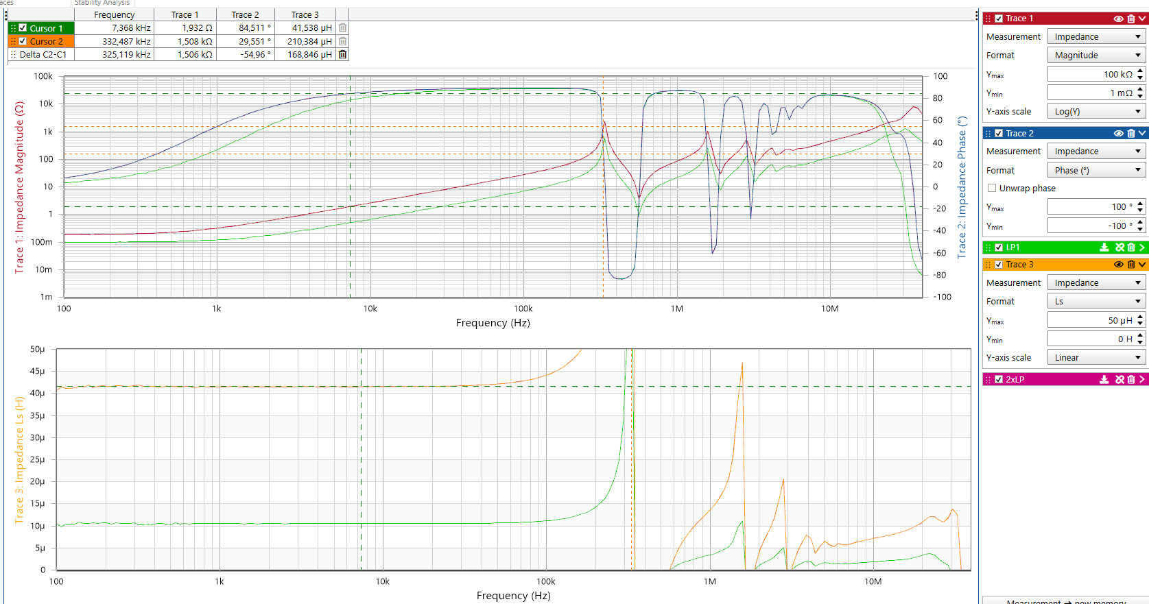