These are the boards that fit within the tiles themselves: https://git.ad8gc.com/ad8gc/DnD_PLCC4/-/blob/main/Schematic.pdf
And these are the "carriers" that'll allow one to snap four tiles in a
row (limited since wider ones got stupid expensive stupid fast for "I probably made a massive error here" :D) https://git.ad8gc.com/ad8gc/DnD_Connector/-/blob/main/Schematic.pdf
Mainly, this is to facilitate testing & debugging -- these are designed
to accommodate a "test bench" of 4x4 tiles (8x8 spaces), and also let me verify that they're short enough to accommodate widening out to 8 or 12 spaces (albeit that'll need an additional 4 or 8 VCC lines, larger
headers, and a wider PCB, not to mention some kind of jumper board or something.
Not shown / drawn up yet (in KiCAD, anyway) is the MCU / Driver "Motherboard". Effectively it's an ATMega328, 3 shift registers (1ea.
for the R,G,B channels) and eight FETs to drive a grid of 8x8 RGB LEDs,
plus power input. (I might be missing a few bits in the description,
it's done up right now as pencil and paper, with a 1-channel MWE done
up on perfboard).
My two design goals were that:
1. These things be easy to use for non-programmers (especially if I
opted to make it into a "product" -- doubt I will, but hey, some people
have more money than time). Ideally, the only programming it's going to
take is defining the room dimensions (essentially the lower-right
corner, given that 0,0 is the upper-left)
2. The tiles be 180-degree rotationally symmetric, to reduce the need
for "single-use" tiles (e.g. wall sections can be either North/South or East/West, rather than JUST N or JUST E). Maybe one day I'll figure out
90 degree symmetry to completely eliminate it.
To accomplish #1; I went with using standard LEDs with multiplexing,
this eliminated two problems I faced with smart/programmable LEDs:
1. Data delivery --> while you need 75% fewer control signals for
"smart" LEDs, things get massively ugly when trying to divide them
into rows and columns. You're either zig-zagging the signal on
every other row; or having a return path on every row, so that
they all start from the left (right). Conversely, with
multiplexing, I just have a grid, with {0,0} being the upper-left
corner.
2. Requires "Special" tiles to facilitate data flow. For example, a
chasm in the middle of the room would still need some kind of
carrier PCB to keep the signal flow across / around the chasm
set-piece. Whereas with the multiplexing, the row/column control
plane (on the carrier-board itself) is otherwise unbroken.
To accomplish #2, I went with some low-profile board-to-board connectors
(cue them NOT being rotationally symmetric when I get the 10 or so I
ordered :) ) ... I want to keep things relatively low-profile, so the individual boards can survive semi-rough handling (e.g. getting stacked
in a case / bin / etc.) that would be problematic with pin-headers. I envision needing a few revisions here, since eventually I want to do
away with the "strips", and replace those with what would amount to individual breakout boards, since the PCBs are otherwise quite big and sparsely populated due to the physical spacing of the game-board.
Likewise, I expect a few revisions on LEDs, etc (I mean, these
common-anode look really nice, but there are *slightly* cheaper options
that don't do the common-anode on-die).
On 12/26/2023 7:42 PM, Dan Purgert wrote:
These are the boards that fit within the tiles themselves:
https://git.ad8gc.com/ad8gc/DnD_PLCC4/-/blob/main/Schematic.pdf
So, these are just lamps+ballast?
And these are the "carriers" that'll allow one to snap four tiles in a
row (limited since wider ones got stupid expensive stupid fast for "I
probably made a massive error here" :D)
https://git.ad8gc.com/ad8gc/DnD_Connector/-/blob/main/Schematic.pdf
Can you, instead, put a small MCU on the "LED boards" and just run power/gnd, and data in/out to each board? Let boards daisy chain their "out" signal
to the neighbor's "in". That way, you can delegate the control of the
lamps to each little MCU as well as limiting the amount of "drive"
required on each (this would scale better than a single driver board).
Note that -- unlike "smart" LEDs -- you don't have to pass a bitmap around but, instead, can send "commands" to each MCU telling each what sort of effect you want *it* to provide for *it's* lamps.
My two design goals were that:
1. These things be easy to use for non-programmers (especially if I
opted to make it into a "product" -- doubt I will, but hey, some people
have more money than time). Ideally, the only programming it's going to
take is defining the room dimensions (essentially the lower-right
corner, given that 0,0 is the upper-left)
2. The tiles be 180-degree rotationally symmetric, to reduce the need
for "single-use" tiles (e.g. wall sections can be either North/South or
East/West, rather than JUST N or JUST E). Maybe one day I'll figure out
90 degree symmetry to completely eliminate it.
I guess I don't understand how these are further "conditioned".
Isn't it just a matrix of indicators? Do the (3Dprinted?) tiles
have additional "character" (e.g., contours, etc.)?
Photo?
To accomplish #1; I went with using standard LEDs with multiplexing,
this eliminated two problems I faced with smart/programmable LEDs:
1. Data delivery --> while you need 75% fewer control signals for
"smart" LEDs, things get massively ugly when trying to divide them
into rows and columns. You're either zig-zagging the signal on
every other row; or having a return path on every row, so that
they all start from the left (right). Conversely, with
multiplexing, I just have a grid, with {0,0} being the upper-left
corner.
Keep in mind that if you multiplex the lamps (which seems like
you may be intending?), then brightness falls with duty cycle.
And, that you need to keep the "frame" rate high enough that
the user doesn't see flicker or visual artifacts as it beats
against the room lighting.
(you may discover that a non-sequential refresh sequence helps
hide visible patterns)
2. Requires "Special" tiles to facilitate data flow. For example, a
chasm in the middle of the room would still need some kind of
carrier PCB to keep the signal flow across / around the chasm
set-piece. Whereas with the multiplexing, the row/column control
plane (on the carrier-board itself) is otherwise unbroken.
To accomplish #2, I went with some low-profile board-to-board connectors
(cue them NOT being rotationally symmetric when I get the 10 or so I
ordered :) ) ... I want to keep things relatively low-profile, so the
individual boards can survive semi-rough handling (e.g. getting stacked
in a case / bin / etc.) that would be problematic with pin-headers. I
envision needing a few revisions here, since eventually I want to do
away with the "strips", and replace those with what would amount to
individual breakout boards, since the PCBs are otherwise quite big and
sparsely populated due to the physical spacing of the game-board.
*If* the 3D "skin" is something that the user can clip on/off the
"lamps", then you could just put a "no feature" tile atop
the lamps so that they can't be seen AND program that MCU to keep
them dark.
Can you, instead, put a small MCU on the "LED boards" and just run power/gnd,
and data in/out to each board? Let boards daisy chain their "out" signal
to the neighbor's "in". That way, you can delegate the control of the
lamps to each little MCU as well as limiting the amount of "drive"
required on each (this would scale better than a single driver board).
"maybe" -- but ultimately the issue is going to be drawing an "area" on
the (in-game) floor where something happened.
USUALLY this is done either by:
(a) counting squares from the "center" of the effect
(b) paper/plastic templates held over the "center" of the effect
Note that -- unlike "smart" LEDs -- you don't have to pass a bitmap around >> but, instead, can send "commands" to each MCU telling each what sort of
effect you want *it* to provide for *it's* lamps.
Which would require that the slave MCU to have a programmable address
(and then there's the problem of address conflicts), and on top of that, there'd need to be a way to convey which slave was at which position of
the "game board", so that the effects would be done correctly.
My two design goals were that:
1. These things be easy to use for non-programmers (especially if I
opted to make it into a "product" -- doubt I will, but hey, some people
have more money than time). Ideally, the only programming it's going to >>> take is defining the room dimensions (essentially the lower-right
corner, given that 0,0 is the upper-left)
2. The tiles be 180-degree rotationally symmetric, to reduce the need
for "single-use" tiles (e.g. wall sections can be either North/South or
East/West, rather than JUST N or JUST E). Maybe one day I'll figure out >>> 90 degree symmetry to completely eliminate it.
I guess I don't understand how these are further "conditioned".
Isn't it just a matrix of indicators? Do the (3Dprinted?) tiles
have additional "character" (e.g., contours, etc.)?
Yep -- Think of the playing surface as a *VERY* low-resolution display screen:
there's only a resolution of 1 pixel / inch (and for testing, I'm
working with a "display" that's all of 8x8 pixels.). The standard
playing surface is effectively a large sheet of graph paper, with a
1-square / inch grid). You draw walls and doors and whatever else on
the board in (wet-erase) marker. The 3d printed tiles are ... well, the
same idea, just, now it's a bunch of plastic pieces that you can set out
in whatever order to build up the room to make things more immersive
for everyone.
Photo?
Here's an example of the 3d-printed tileset. The room here is comprised
of nine (9) individual 3d-printed tiles (All are 2x2 playing spaces,
even though the walls eat half the space, to keep the real-world
dimensions "correct") : https://www.fatdragongames.com/images/FDG0160AW7.jpg
To accomplish #1; I went with using standard LEDs with multiplexing,
this eliminated two problems I faced with smart/programmable LEDs:
1. Data delivery --> while you need 75% fewer control signals for
"smart" LEDs, things get massively ugly when trying to divide them >>> into rows and columns. You're either zig-zagging the signal on
every other row; or having a return path on every row, so that
they all start from the left (right). Conversely, with
multiplexing, I just have a grid, with {0,0} being the upper-left >>> corner.
Keep in mind that if you multiplex the lamps (which seems like
you may be intending?), then brightness falls with duty cycle.
And, that you need to keep the "frame" rate high enough that
the user doesn't see flicker or visual artifacts as it beats
against the room lighting.
Yep, the framerate (and brightness) should be fine; at least for this
initial testing size. I mean, let's face it, this is already 64 LED
packages with "just" an 8x8 grid; "testing" with 16x16 (256 LEDs) or
24*24 (576 LEDs) would just be madness :)
(you may discover that a non-sequential refresh sequence helps
hide visible patterns)
2. Requires "Special" tiles to facilitate data flow. For example, a >>> chasm in the middle of the room would still need some kind of
carrier PCB to keep the signal flow across / around the chasm
set-piece. Whereas with the multiplexing, the row/column control >>> plane (on the carrier-board itself) is otherwise unbroken.
To accomplish #2, I went with some low-profile board-to-board connectors >>> (cue them NOT being rotationally symmetric when I get the 10 or so I
ordered :) ) ... I want to keep things relatively low-profile, so the
individual boards can survive semi-rough handling (e.g. getting stacked
in a case / bin / etc.) that would be problematic with pin-headers. I
envision needing a few revisions here, since eventually I want to do
away with the "strips", and replace those with what would amount to
individual breakout boards, since the PCBs are otherwise quite big and
sparsely populated due to the physical spacing of the game-board.
*If* the 3D "skin" is something that the user can clip on/off the
"lamps", then you could just put a "no feature" tile atop
the lamps so that they can't be seen AND program that MCU to keep
them dark.
Sure, I could do that (maybe). But I *really* want to avoid making
"special cases" for myself at this point (or, frankly, at any point).
As it stands, if there were a feature that breaks the "standard tile"
for some reason (e.g. a chasm, or collapsed floor, or ... whatever),
it's not going to have any effect on any other LED in the given
row/column.
Maybe someday I'll figure it out (or scrap this approach as subpar, and revise the whole thing ...)
On 12/26/2023 10:17 PM, Dan Purgert wrote:
Can you, instead, put a small MCU on the "LED boards" and just run
power/gnd, and data in/out to each board? Let boards daisy chain
their "out" signal to the neighbor's "in". That way, you can
delegate the control of the lamps to each little MCU as well as
limiting the amount of "drive" required on each (this would scale
better than a single driver board).
"maybe" -- but ultimately the issue is going to be drawing an "area" on
the (in-game) floor where something happened.
USUALLY this is done either by:
(a) counting squares from the "center" of the effect
(b) paper/plastic templates held over the "center" of the effect
I'm not advocating for the MCUs to know anything about the game
or "what's (currently) happening". "Something" drives the array,
knowing where every "feature" is located and how to run any
animations -- by directing the associated MCUs to "do this"
or "do that".
The "something" operates at a higher level of abstraction; it
doesn't deal with individual lamps but, rather, with effects
that it delegates to the MCUs in the "regions of interest".
So (keep in mind, I have no idea of DnD gameplay), if there
was an explosion at (4,2) at time t, it would direct the
MCU *at* (4,2) to run the explosion animation at time t.
The "something" (controller, for want of better word) would
know that the effect will take N time units *in* (4,2) and
then want to "dissipate" into the surrounding tiles at time
t=N.
Note that -- unlike "smart" LEDs -- you don't have to pass a bitmap around >>> but, instead, can send "commands" to each MCU telling each what sort of
effect you want *it* to provide for *it's* lamps.
Which would require that the slave MCU to have a programmable address
(and then there's the problem of address conflicts), and on top of that,
there'd need to be a way to convey which slave was at which position of
the "game board", so that the effects would be done correctly.
No. Each MCU takes the first N bits of data coming in and
assumes it is intended for *it's* use. The balance are passed
through to the next MCU "downstream".
As there is only one "downstream" neighbor, each MCU has nothing
to decide -- just pass the balance along.
Scaling "widthwise" just means making longer data streams.
Scaling "heightwise" would mean adding additional serial
streams from the controller.
My two design goals were that:
1. These things be easy to use for non-programmers (especially if I
opted to make it into a "product" -- doubt I will, but hey, some people >>>> have more money than time). Ideally, the only programming it's going to >>>> take is defining the room dimensions (essentially the lower-right
corner, given that 0,0 is the upper-left)
2. The tiles be 180-degree rotationally symmetric, to reduce the need
for "single-use" tiles (e.g. wall sections can be either North/South or >>>> East/West, rather than JUST N or JUST E). Maybe one day I'll figure out >>>> 90 degree symmetry to completely eliminate it.
I guess I don't understand how these are further "conditioned".
Isn't it just a matrix of indicators? Do the (3Dprinted?) tiles
have additional "character" (e.g., contours, etc.)?
Yep -- Think of the playing surface as a *VERY* low-resolution
display screen: there's only a resolution of 1 pixel / inch (and for
testing, I'm working with a "display" that's all of 8x8 pixels.).
The standard playing surface is effectively a large sheet of graph
paper, with a 1-square / inch grid). You draw walls and doors and
whatever else on the board in (wet-erase) marker. The 3d printed
tiles are ... well, the same idea, just, now it's a bunch of plastic
pieces that you can set out in whatever order to build up the room to
make things more immersive for everyone.
So, there are N different *types* of "tiles"? I.e., one that is
a piece of lake, another that is the side of a mountain, etc.?
And, the plastic is permanently part of the tile?
I.e., so, you could decide which effects can occur in each
type of tile. E.g., a 'splash' can't occur on dry land;
an explosion dissipates when it runs into a mountain, etc.
Photo?
Here's an example of the 3d-printed tileset. The room here is comprised
of nine (9) individual 3d-printed tiles (All are 2x2 playing spaces,
even though the walls eat half the space, to keep the real-world
dimensions "correct") : https://www.fatdragongames.com/images/FDG0160AW7.jpg
So, you'd have 36 tri-color LEDs in that same space?
I assume *under* the tile? So, the floor would have to
be transparent/translucent?
What would you do with 36 lamps in such a room? Would you
try to indicate the positions of some number of players
(each a different color?) within? Or, the motion of a
player THROUGH the space?
[I'm trying to get an idea of what the effects would be like,
in terms of complexity]
To accomplish #1; I went with using standard LEDs with multiplexing,
this eliminated two problems I faced with smart/programmable LEDs:
1. Data delivery --> while you need 75% fewer control signals for
"smart" LEDs, things get massively ugly when trying to divide them >>>> into rows and columns. You're either zig-zagging the signal on >>>> every other row; or having a return path on every row, so that >>>> they all start from the left (right). Conversely, with
multiplexing, I just have a grid, with {0,0} being the upper-left >>>> corner.
Keep in mind that if you multiplex the lamps (which seems like
you may be intending?), then brightness falls with duty cycle.
And, that you need to keep the "frame" rate high enough that
the user doesn't see flicker or visual artifacts as it beats
against the room lighting.
Yep, the framerate (and brightness) should be fine; at least for this
initial testing size. I mean, let's face it, this is already 64 LED
packages with "just" an 8x8 grid; "testing" with 16x16 (256 LEDs) or
24*24 (576 LEDs) would just be madness :)
How good are your coding skills? Could you emulate it
on a CRT to get a feel for what it would look like?
(you may discover that a non-sequential refresh sequence helps
hide visible patterns)
2. Requires "Special" tiles to facilitate data flow. For example, a >>>> chasm in the middle of the room would still need some kind of
carrier PCB to keep the signal flow across / around the chasm
set-piece. Whereas with the multiplexing, the row/column control >>>> plane (on the carrier-board itself) is otherwise unbroken.
To accomplish #2, I went with some low-profile board-to-board connectors >>>> (cue them NOT being rotationally symmetric when I get the 10 or so I
ordered :) ) ... I want to keep things relatively low-profile, so the
individual boards can survive semi-rough handling (e.g. getting stacked >>>> in a case / bin / etc.) that would be problematic with pin-headers. I >>>> envision needing a few revisions here, since eventually I want to do
away with the "strips", and replace those with what would amount to
individual breakout boards, since the PCBs are otherwise quite big and >>>> sparsely populated due to the physical spacing of the game-board.
*If* the 3D "skin" is something that the user can clip on/off the
"lamps", then you could just put a "no feature" tile atop
the lamps so that they can't be seen AND program that MCU to keep
them dark.
Sure, I could do that (maybe). But I *really* want to avoid making
"special cases" for myself at this point (or, frankly, at any point).
As it stands, if there were a feature that breaks the "standard tile"
for some reason (e.g. a chasm, or collapsed floor, or ... whatever),
it's not going to have any effect on any other LED in the given
row/column.
In my scenario, the "gap" would just be an MCU told "do nothing"
(stay dark?) but continue to pass the BALANCE of the data stream
across to your downstream neighbor.
Maybe someday I'll figure it out (or scrap this approach as subpar, and
revise the whole thing ...)
Is there a nominal "game board size"? I.e., could you
standardize on 8x8 "subpanels" -- onto which the
plastic parts could be placed for textural effect?
onsdag den 27. december 2023 kl. 07.52.35 UTC+1 skrev Don Y:
On 12/26/2023 10:17 PM, Dan Purgert wrote:
I'm not advocating for the MCUs to know anything about the gameCan you, instead, put a small MCU on the "LED boards" and just run power/gnd,
and data in/out to each board? Let boards daisy chain their "out" signal >>>> to the neighbor's "in". That way, you can delegate the control of the
lamps to each little MCU as well as limiting the amount of "drive"
required on each (this would scale better than a single driver board).
"maybe" -- but ultimately the issue is going to be drawing an "area" on
the (in-game) floor where something happened.
USUALLY this is done either by:
(a) counting squares from the "center" of the effect
(b) paper/plastic templates held over the "center" of the effect
or "what's (currently) happening". "Something" drives the array,
knowing where every "feature" is located and how to run any
animations -- by directing the associated MCUs to "do this"
or "do that".
The "something" operates at a higher level of abstraction; it
doesn't deal with individual lamps but, rather, with effects
that it delegates to the MCUs in the "regions of interest".
So (keep in mind, I have no idea of DnD gameplay), if there
was an explosion at (4,2) at time t, it would direct the
MCU *at* (4,2) to run the explosion animation at time t.
The "something" (controller, for want of better word) would
know that the effect will take N time units *in* (4,2) and
then want to "dissipate" into the surrounding tiles at time
t=N.
So, the MCU at (3,2) -- just to the left of the origin of
the explosion -- would be told to run the "explosion off
to your right" animation at t=N. The MCU at (5,2 would be
told to run "explosion off to your LEFT" at t=N. The
MCU at (4,3) would be told "explosion above", etc.
The controller would just have to know (algorithmically)
how an effect propagates into adjacent tiles and which
effects it initiates IN those tiles as a result.
The value *you* would add is scripting each of these
effects *in* the specific MCUs AND their "side effects"
in adjacent MCUs (based on board geometry).
The user would just be concerned with defining which
tile is where. And, "something" would have to decide
how the game was progressing (so it would know which effects
to initiate, and where)
[Again, I am only GUESSING as to how "play" happens.]
No. Each MCU takes the first N bits of data coming in andNote that -- unlike "smart" LEDs -- you don't have to pass a bitmap around >>>> but, instead, can send "commands" to each MCU telling each what sort of >>>> effect you want *it* to provide for *it's* lamps.
Which would require that the slave MCU to have a programmable address
(and then there's the problem of address conflicts), and on top of that, >>> there'd need to be a way to convey which slave was at which position of
the "game board", so that the effects would be done correctly.
assumes it is intended for *it's* use. The balance are passed
through to the next MCU "downstream".
As there is only one "downstream" neighbor, each MCU has nothing
to decide -- just pass the balance along.
Scaling "widthwise" just means making longer data streams.
Scaling "heightwise" would mean adding additional serial
streams from the controller.
then you are back to having to send the whole bitmap to change
a single pixel, like smart LEDs ...
though you could use that scheme during initialization to give each node a unique address, after which each node will only react to its own address and pass along everything else
USUALLY this is done either by:
(a) counting squares from the "center" of the effect
(b) paper/plastic templates held over the "center" of the effect
I'm not advocating for the MCUs to know anything about the game
or "what's (currently) happening". "Something" drives the array,
knowing where every "feature" is located and how to run any
animations -- by directing the associated MCUs to "do this"
or "do that".
The "something" operates at a higher level of abstraction; it
doesn't deal with individual lamps but, rather, with effects
that it delegates to the MCUs in the "regions of interest".
So (keep in mind, I have no idea of DnD gameplay), if there
was an explosion at (4,2) at time t, it would direct the
MCU *at* (4,2) to run the explosion animation at time t.
The "something" (controller, for want of better word) would
know that the effect will take N time units *in* (4,2) and
then want to "dissipate" into the surrounding tiles at time
t=N.
Close enough :). The issue is, now I'm tossing an MCU onto each tile,
to try making them "smarter", and adding complexity to the "master"
board to accommodate selecting which row/column is active.
It's certainly an option; but on the other hand, "dumb LEDs" where a MCU
can just act as a CPU and push out "turn on 4,2" with a BJT and a shift register.
Note that -- unlike "smart" LEDs -- you don't have to pass a bitmap around >>>> but, instead, can send "commands" to each MCU telling each what sort of >>>> effect you want *it* to provide for *it's* lamps.
Which would require that the slave MCU to have a programmable address
(and then there's the problem of address conflicts), and on top of that, >>> there'd need to be a way to convey which slave was at which position of
the "game board", so that the effects would be done correctly.
No. Each MCU takes the first N bits of data coming in and
assumes it is intended for *it's* use. The balance are passed
through to the next MCU "downstream".
As there is only one "downstream" neighbor, each MCU has nothing
to decide -- just pass the balance along.
Scaling "widthwise" just means making longer data streams.
Scaling "heightwise" would mean adding additional serial
streams from the controller.
Ah, so "sorta" like the idea behind the WS2812 driver chips, but using a selector switch (for example) to enable the data to "Row N"
So, there are N different *types* of "tiles"? I.e., one that is
a piece of lake, another that is the side of a mountain, etc.?
And, the plastic is permanently part of the tile?
Yeah, *MOST* of them are quite likely "floor style, variant X" (e.g. a "dungeon" set may have 4 "open floor" variants -- "empty" [just four flagstones], "some rubble" in a space, or perhaps something like "trap
door" or "collapsed floor"). Then there's also the "border" pieces with walls (and doors, etc).
I.e., so, you could decide which effects can occur in each
type of tile. E.g., a 'splash' can't occur on dry land;
an explosion dissipates when it runs into a mountain, etc.
"Sort of" but at the present time, I'm not planning anything quite so
complex as to know what the floor features are.
Photo?
Here's an example of the 3d-printed tileset. The room here is comprised >>> of nine (9) individual 3d-printed tiles (All are 2x2 playing spaces,
even though the walls eat half the space, to keep the real-world
dimensions "correct") : https://www.fatdragongames.com/images/FDG0160AW7.jpg
So, you'd have 36 tri-color LEDs in that same space?
I assume *under* the tile? So, the floor would have to
be transparent/translucent?
Yep, or a little hole in the space where a player piece would be
standing. PROBABLY a hole, since painting the tiles wouldn't become problematic (I mean, let's face it, 3D-Printers are entirely uniform
colors, and while that's perfectly fine for a testing phase ... )
What would you do with 36 lamps in such a room? Would you
try to indicate the positions of some number of players
(each a different color?) within? Or, the motion of a
player THROUGH the space?
No. Taking that little room shown in the picture there, maybe the
players set off some kind of trap from the door in the "north" wall that sprayed fire at them when they tried opening it.
So this is the grid, with the "W" representing the spaces with walls,
"D" being the doors, and the "0" being the tiles a character might be
on.
W W D D W W
W 0 0 0 0 W
D 0 0 0 0 D
D 0 0 0 0 D
W 0 0 0 0 W
W 0 0 0 0 W
W W W W W W
Here, we've switched "on" the fire effect ('1's)
W W D D W W
W 0 1 1 0 W
D 0 1 1 0 D
D 1 1 1 1 D
W 0 0 0 0 W
W 0 0 0 0 W
W W W W W W
So, any character that happened to be standing in the "1" spaces would
get hurt.
[I'm trying to get an idea of what the effects would be like,
in terms of complexity]
For now, they're gonna be really simple (just solid red). Eventually, probably replace the shift-registers with proper LED drivers, that can
help do brightness control, etc (so I can mix the RGB channels and get a
more "fire" looking color orange, or "electric blue", and so on)
To accomplish #1; I went with using standard LEDs with multiplexing, >>>>> this eliminated two problems I faced with smart/programmable LEDs:
1. Data delivery --> while you need 75% fewer control signals for >>>>> "smart" LEDs, things get massively ugly when trying to divide them
into rows and columns. You're either zig-zagging the signal on >>>>> every other row; or having a return path on every row, so that >>>>> they all start from the left (right). Conversely, with
multiplexing, I just have a grid, with {0,0} being the upper-left
corner.
Keep in mind that if you multiplex the lamps (which seems like
you may be intending?), then brightness falls with duty cycle.
And, that you need to keep the "frame" rate high enough that
the user doesn't see flicker or visual artifacts as it beats
against the room lighting.
Yep, the framerate (and brightness) should be fine; at least for this
initial testing size. I mean, let's face it, this is already 64 LED
packages with "just" an 8x8 grid; "testing" with 16x16 (256 LEDs) or
24*24 (576 LEDs) would just be madness :)
How good are your coding skills? Could you emulate it
on a CRT to get a feel for what it would look like?
good enough, but I don't have a CRT to hand.
I've done it small-scale
with protoboard and 64 (white) LEDs, and it came out well enough. Plan
for the week is to drop by the hardware store and pick up one of those
12x12 project panels (assuming I don't have any suitable plywood hanging
out around the house already) and put some LEDs on a big grid.
(you may discover that a non-sequential refresh sequence helps
hide visible patterns)
2. Requires "Special" tiles to facilitate data flow. For example, a >>>>> chasm in the middle of the room would still need some kind of >>>>> carrier PCB to keep the signal flow across / around the chasm >>>>> set-piece. Whereas with the multiplexing, the row/column control
plane (on the carrier-board itself) is otherwise unbroken.
To accomplish #2, I went with some low-profile board-to-board connectors >>>>> (cue them NOT being rotationally symmetric when I get the 10 or so I >>>>> ordered :) ) ... I want to keep things relatively low-profile, so the >>>>> individual boards can survive semi-rough handling (e.g. getting stacked >>>>> in a case / bin / etc.) that would be problematic with pin-headers. I >>>>> envision needing a few revisions here, since eventually I want to do >>>>> away with the "strips", and replace those with what would amount to
individual breakout boards, since the PCBs are otherwise quite big and >>>>> sparsely populated due to the physical spacing of the game-board.
*If* the 3D "skin" is something that the user can clip on/off the
"lamps", then you could just put a "no feature" tile atop
the lamps so that they can't be seen AND program that MCU to keep
them dark.
Sure, I could do that (maybe). But I *really* want to avoid making
"special cases" for myself at this point (or, frankly, at any point).
As it stands, if there were a feature that breaks the "standard tile"
for some reason (e.g. a chasm, or collapsed floor, or ... whatever),
it's not going to have any effect on any other LED in the given
row/column.
In my scenario, the "gap" would just be an MCU told "do nothing"
(stay dark?) but continue to pass the BALANCE of the data stream
across to your downstream neighbor.
Yeah, but the thing you're not accounting for is that a "Ruined Floor"
piece isn't the "standard(tm)" nominal 2" square -- rather, it'll have a missing corner (or more) so that there's a visual hole in the floor. So
I'd need a special PCB for that piece (or any similar piece that "breaks through" the plane of the floor.
With the current multiplexed approach, those "odd" tiles don't cause any trouble (other than an extra ring of non-effect that's suboptimal, but I
can live with that, since it's less engineering
Maybe someday I'll figure it out (or scrap this approach as subpar, and
revise the whole thing ...)
Is there a nominal "game board size"? I.e., could you
standardize on 8x8 "subpanels" -- onto which the
plastic parts could be placed for textural effect?
FOR NOW, it's 4x4 tiles (64 LEDs), because that fits really well into
two bytes, and I can keep it all in my head. EVENTUALLY I want to accommodate 8x8 tiles (256 LEDs) ...
then you are back to having to send the whole bitmap to changeNo. "You" wouldn't change a "single pixel"; the *effect*,
a single pixel, like smart LEDs ...
running *in* one of the MCUs (having already been told
"run this effect") would know which pixel to change, and when.
I.e., the animation can run FASTER than the data rate because
you encode the animation (effect) in the datum that was delivered
to THAT MCU.
but you still have to send stream as long as the number of mcus, you can't just send single a command addressed
to a specific one
On 12/27/2023 6:32 AM, Dan Purgert wrote:
On 2023-12-27, Don Y wrote:
[...]
What would you do with 36 lamps in such a room? Would you
try to indicate the positions of some number of players
(each a different color?) within? Or, the motion of a
player THROUGH the space?
No. Taking that little room shown in the picture there, maybe the
players set off some kind of trap from the door in the "north" wall that
sprayed fire at them when they tried opening it.
So this is the grid, with the "W" representing the spaces with walls,
"D" being the doors, and the "0" being the tiles a character might be
on.
W W D D W W
W 0 0 0 0 W
D 0 0 0 0 D
D 0 0 0 0 D
W 0 0 0 0 W
W 0 0 0 0 W
W W W W W W
Here, we've switched "on" the fire effect ('1's)
W W D D W W
W 0 1 1 0 W
D 0 1 1 0 D
D 1 1 1 1 D
W 0 0 0 0 W
W 0 0 0 0 W
W W W W W W
So, any character that happened to be standing in the "1" spaces would
get hurt.
So, characters can occupy any (1,1) cell? I.e., in the example, above,
every 0 (or 1) could have a character -- as well as "in" the doorways?
How do players distinguish THEIR character from others (and effects)?
Or, are their characters real bits of plastic sitting ON the tile?
[I'm trying to get an idea of what the effects would be like,
in terms of complexity]
For now, they're gonna be really simple (just solid red). Eventually,
probably replace the shift-registers with proper LED drivers, that can
help do brightness control, etc (so I can mix the RGB channels and get a
more "fire" looking color orange, or "electric blue", and so on)
The downside of putting the effects in the MCUs is that you'd
either need to reflash them each time you tried a new effect
*or* design them with RAM in which the effect could be stored
(DL at game initialization?)
[I took the latter approach]
To accomplish #1; I went with using standard LEDs with multiplexing, >>>>>> this eliminated two problems I faced with smart/programmable LEDs: >>>>>>
1. Data delivery --> while you need 75% fewer control signals for >>>>>> "smart" LEDs, things get massively ugly when trying to
divide them into rows and columns. You're either
zig-zagging the signal on every other row; or having a
return path on every row, so that they all start from
the left (right). Conversely, with multiplexing, I just
have a grid, with {0,0} being the upper-left corner.
Keep in mind that if you multiplex the lamps (which seems like
you may be intending?), then brightness falls with duty cycle.
And, that you need to keep the "frame" rate high enough that
the user doesn't see flicker or visual artifacts as it beats
against the room lighting.
Yep, the framerate (and brightness) should be fine; at least for this
initial testing size. I mean, let's face it, this is already 64 LED
packages with "just" an 8x8 grid; "testing" with 16x16 (256 LEDs) or
24*24 (576 LEDs) would just be madness :)
How good are your coding skills? Could you emulate it
on a CRT to get a feel for what it would look like?
good enough, but I don't have a CRT to hand.
CRT == LCD
I've done it small-scale
with protoboard and 64 (white) LEDs, and it came out well enough. Plan
for the week is to drop by the hardware store and pick up one of those
12x12 project panels (assuming I don't have any suitable plywood hanging
out around the house already) and put some LEDs on a big grid.
(you may discover that a non-sequential refresh sequence helps
hide visible patterns)
2. Requires "Special" tiles to facilitate data flow. For example, a
chasm in the middle of the room would still need some
kind of carrier PCB to keep the signal flow across /
around the chasm set-piece. Whereas with the
multiplexing, the row/column control plane (on the
carrier-board itself) is otherwise unbroken.
To accomplish #2, I went with some low-profile board-to-board connectors >>>>>> (cue them NOT being rotationally symmetric when I get the 10 or so I >>>>>> ordered :) ) ... I want to keep things relatively low-profile, so the >>>>>> individual boards can survive semi-rough handling (e.g. getting stacked >>>>>> in a case / bin / etc.) that would be problematic with pin-headers. I >>>>>> envision needing a few revisions here, since eventually I want to do >>>>>> away with the "strips", and replace those with what would amount to >>>>>> individual breakout boards, since the PCBs are otherwise quite big and >>>>>> sparsely populated due to the physical spacing of the game-board.
*If* the 3D "skin" is something that the user can clip on/off the
"lamps", then you could just put a "no feature" tile atop
the lamps so that they can't be seen AND program that MCU to keep
them dark.
Sure, I could do that (maybe). But I *really* want to avoid making
"special cases" for myself at this point (or, frankly, at any point).
As it stands, if there were a feature that breaks the "standard tile"
for some reason (e.g. a chasm, or collapsed floor, or ... whatever),
it's not going to have any effect on any other LED in the given
row/column.
In my scenario, the "gap" would just be an MCU told "do nothing"
(stay dark?) but continue to pass the BALANCE of the data stream
across to your downstream neighbor.
Yeah, but the thing you're not accounting for is that a "Ruined Floor"
piece isn't the "standard(tm)" nominal 2" square -- rather, it'll have a
missing corner (or more) so that there's a visual hole in the floor. So
I'd need a special PCB for that piece (or any similar piece that "breaks
through" the plane of the floor.
Wouldn't it just be dark? The plastic piece atop it doesn't magically
become ruined...
With the current multiplexed approach, those "odd" tiles don't cause any
trouble (other than an extra ring of non-effect that's suboptimal, but I
can live with that, since it's less engineering
Why can't one of the "effects" commanded to an MCU encode the
same appearance/behavior?
But a ruin / chasm / etc tile may only be
S S OR S S
- - - S
(with the "-" indicating the missing space). The "broken" edge then
(i.e. touching the "-") will be printed up to look like the stone floor
cracked, or if it's an abandoned wooden structure, you'll have a bit of
floor joist sticking out, etc.
So, you'd not want the PCB beneath to be exposed in those cases?
Could the PCB be potted in a black substance so only the actual
LED is exposed to daylight (and easily ignored if that "corner"
is meant to not exist?)
So this is the grid, with the "W" representing the spaces with walls,
"D" being the doors, and the "0" being the tiles a character might be
on.
W W D D W W
W 0 0 0 0 W
D 0 0 0 0 D
D 0 0 0 0 D
W 0 0 0 0 W
W 0 0 0 0 W
W W W W W W
Here, we've switched "on" the fire effect ('1's)
W W D D W W
W 0 1 1 0 W
D 0 1 1 0 D
D 1 1 1 1 D
W 0 0 0 0 W
W 0 0 0 0 W
W W W W W W
So, any character that happened to be standing in the "1" spaces would
get hurt.
So, characters can occupy any (1,1) cell? I.e., in the example, above,
every 0 (or 1) could have a character -- as well as "in" the doorways?
Yep
How do players distinguish THEIR character from others (and effects)?
Or, are their characters real bits of plastic sitting ON the tile?
Yep, figurines or even just tokens stolen from other games (e.g.
"Trouble" or "Monopoly", etc). Anything that the players can remember as "them" or "that Goblin I'm fighting" ...
[I'm trying to get an idea of what the effects would be like,
in terms of complexity]
For now, they're gonna be really simple (just solid red). Eventually,
probably replace the shift-registers with proper LED drivers, that can
help do brightness control, etc (so I can mix the RGB channels and get a >>> more "fire" looking color orange, or "electric blue", and so on)
The downside of putting the effects in the MCUs is that you'd
either need to reflash them each time you tried a new effect
*or* design them with RAM in which the effect could be stored
(DL at game initialization?)
[I took the latter approach]
The "Effects" are pretty static in general terms (e.g. that flame-jet
trap is ALWAYS that shape when on the grid. If it's 45 degrees to the
grid, then it'd just look like this:
0 0 0 0 0
0 1 0 0 0
0 1 1 0 0
0 1 1 1 0
0 0 0 0 0
Other effects might approximate a circle:
0 0 0 0 0 0 0 0
0 0 0 1 1 0 0 0
0 0 1 1 1 1 0 0
0 1 1 1 1 1 1 0
0 1 1 1 1 1 1 0
0 0 1 1 1 1 0 0
0 0 0 1 1 0 0 0
0 0 0 0 0 0 0 0
Or just a line.
After that, it's just defining the color (e.g. an explosion would be
some kind of orange color; or a broken vial of acid might be green,
etc.) Ultimately; it really is just "shape and color".
Although your (possibly snipped) idea about "other effects" is certainly interesting (torches on the walls sounds pretty neat, tbh).
To accomplish #1; I went with using standard LEDs with multiplexing, >>>>>>> this eliminated two problems I faced with smart/programmable LEDs: >>>>>>>
1. Data delivery --> while you need 75% fewer control signals for >>>>>>> "smart" LEDs, things get massively ugly when trying to >>>>>>> divide them into rows and columns. You're either
zig-zagging the signal on every other row; or having a >>>>>>> return path on every row, so that they all start from
the left (right). Conversely, with multiplexing, I just >>>>>>> have a grid, with {0,0} being the upper-left corner.
Keep in mind that if you multiplex the lamps (which seems like
you may be intending?), then brightness falls with duty cycle.
And, that you need to keep the "frame" rate high enough that
the user doesn't see flicker or visual artifacts as it beats
against the room lighting.
Yep, the framerate (and brightness) should be fine; at least for this >>>>> initial testing size. I mean, let's face it, this is already 64 LED >>>>> packages with "just" an 8x8 grid; "testing" with 16x16 (256 LEDs) or >>>>> 24*24 (576 LEDs) would just be madness :)
How good are your coding skills? Could you emulate it
on a CRT to get a feel for what it would look like?
good enough, but I don't have a CRT to hand.
CRT == LCD
Nuh uh. CRT is a scanning electron gun in a vacuum tube (and wicked
heavy).
But yes, I should have at least one or two old monitors that'll still
accept VGA inputs, if that's what you meant?
Yeah, but the thing you're not accounting for is that a "Ruined Floor"
piece isn't the "standard(tm)" nominal 2" square -- rather, it'll have a >>> missing corner (or more) so that there's a visual hole in the floor. So >>> I'd need a special PCB for that piece (or any similar piece that "breaks >>> through" the plane of the floor.
Wouldn't it just be dark? The plastic piece atop it doesn't magically
become ruined...
No, it's printed that way. Normally a "full tile" is 2x2 playable
spaces, i.e.
S S
S S
But a ruin / chasm / etc tile may only be
S S OR S S
- - - S
(with the "-" indicating the missing space). The "broken" edge then
(i.e. touching the "-") will be printed up to look like the stone floor cracked, or if it's an abandoned wooden structure, you'll have a bit of
floor joist sticking out, etc.
Ultimately, that "edge" part of the feature doesn't accommodate the
shape of my LED board; and even if I did make a custom board for those features, the current design puts the connector dead-center on the LED carrier. Moving those connection points around is potentially possible,
but I'd rather get the general idea into a "working" state before
changing too many other things.
With the current multiplexed approach, those "odd" tiles don't cause any >>> trouble (other than an extra ring of non-effect that's suboptimal, but I >>> can live with that, since it's less engineering
Why can't one of the "effects" commanded to an MCU encode the
same appearance/behavior?
Right now, a single board is basically $2 assembled (4x LEDs packages,
1x connector, 12x resistors); plus something like $6 for the
"motherboard" (ATMega328 + 3x shift registers + 8x BJTs +
caps/resistors/etc. as required).
Even adding "just" an ATTiny 202 is upping each slave board's price by
25% or so (and that's ignoring any data-integrity stuff like switching
to e.g. RS485, etc). I'm not saying I won't be going there; but seems a
bit premature to jump into that for an idea that may have other flaws elsewhere.
On 12/27/2023 11:00 AM, Dan Purgert wrote:
So this is the grid, with the "W" representing the spaces with walls,
"D" being the doors, and the "0" being the tiles a character might be
on.
W W D D W W
W 0 0 0 0 W
D 0 0 0 0 D
D 0 0 0 0 D
W 0 0 0 0 W
W 0 0 0 0 W
W W W W W W
Here, we've switched "on" the fire effect ('1's)
W W D D W W
W 0 1 1 0 W
D 0 1 1 0 D
D 1 1 1 1 D
W 0 0 0 0 W
W 0 0 0 0 W
W W W W W W
So, any character that happened to be standing in the "1" spaces would >>>> get hurt.
So, characters can occupy any (1,1) cell? I.e., in the example, above,
every 0 (or 1) could have a character -- as well as "in" the doorways?
Yep
How do players distinguish THEIR character from others (and effects)?
Or, are their characters real bits of plastic sitting ON the tile?
Yep, figurines or even just tokens stolen from other games (e.g.
"Trouble" or "Monopoly", etc). Anything that the players can remember as
"them" or "that Goblin I'm fighting" ...
OK. I keep thinking in terms of video games. <frown>
So, the (your) tiles are just meant to ENHANCE the visuals,
not *be* the visuals.
[I'm trying to get an idea of what the effects would be like,
in terms of complexity]
For now, they're gonna be really simple (just solid red). Eventually, >>>> probably replace the shift-registers with proper LED drivers, that can >>>> help do brightness control, etc (so I can mix the RGB channels and get a >>>> more "fire" looking color orange, or "electric blue", and so on)
The downside of putting the effects in the MCUs is that you'd
either need to reflash them each time you tried a new effect
*or* design them with RAM in which the effect could be stored
(DL at game initialization?)
[I took the latter approach]
The "Effects" are pretty static in general terms (e.g. that flame-jet
trap is ALWAYS that shape when on the grid. If it's 45 degrees to the
grid, then it'd just look like this:
0 0 0 0 0
0 1 0 0 0
0 1 1 0 0
0 1 1 1 0
0 0 0 0 0
Other effects might approximate a circle:
0 0 0 0 0 0 0 0
0 0 0 1 1 0 0 0
0 0 1 1 1 1 0 0
0 1 1 1 1 1 1 0
0 1 1 1 1 1 1 0
0 0 1 1 1 1 0 0
0 0 0 1 1 0 0 0
0 0 0 0 0 0 0 0
Or just a line.
OK. I was assuming the "flame jet" would be an animated *sequence*... several consecutive "frames" arranged to generate an "effect".
So, it might be:
0 0 0 0 0
0 0 0 0 0
0 0 0 0 0
0 0 0 0 0
0 0 0 0 0
0 0 0 0 0
0 0 0 1 0
0 0 0 0 0
0 0 0 0 0
0 0 0 0 0
0 0 0 0 0
0 0 1 1 0
0 0 0 1 0
0 0 0 0 0
0 0 0 0 0
0 0 0 0 0
0 0 1 0 0
0 0 1 1 0
0 0 0 0 0
0 0 0 0 0
0 0 0 0 0
0 1 1 0 0
0 0 1 1 0
0 0 0 1 0
0 0 0 0 0
0 0 0 0 0
0 1 0 0 0
0 1 1 0 0
0 0 1 1 0
0 0 0 0 0
0 0 0 0 0
0 1 0 0 0
0 1 1 0 0
0 1 1 1 0
0 0 0 0 0
in half-second (?) snapshots.
[This is why I was suggesting the MCU as it would allow the
data rate to be lowered so the controller just had to say
"do this" instead of actually *doing* it in place of the MCU]
[...[
No, it's printed that way. Normally a "full tile" is 2x2 playable
spaces, i.e.
S S
S S
You speak as if this is a *standard* (?) and not just an attribute of
your particular implementation?
But a ruin / chasm / etc tile may only be
S S OR S S
- - - S
(with the "-" indicating the missing space). The "broken" edge then
(i.e. touching the "-") will be printed up to look like the stone floor
cracked, or if it's an abandoned wooden structure, you'll have a bit of
floor joist sticking out, etc.
So, you'd not want the PCB beneath to be exposed in those cases?
Could the PCB be potted in a black substance so only the actual
LED is exposed to daylight (and easily ignored if that "corner"
is meant to not exist?)
Ultimately, that "edge" part of the feature doesn't accommodate the
shape of my LED board; and even if I did make a custom board for those
features, the current design puts the connector dead-center on the LED
carrier. Moving those connection points around is potentially possible,
but I'd rather get the general idea into a "working" state before
changing too many other things.
You'd, presumably, also have to deal with the case where *two* corners
(or three!) were missing -- and *which* corners (e.g., opposite or adjacent)
I.e., there's a big incentive for you to find a way to NOT need
to address that on your PCB.
With the current multiplexed approach, those "odd" tiles don't cause any >>>> trouble (other than an extra ring of non-effect that's suboptimal, but I >>>> can live with that, since it's less engineering
Why can't one of the "effects" commanded to an MCU encode the
same appearance/behavior?
Right now, a single board is basically $2 assembled (4x LEDs packages,
1x connector, 12x resistors); plus something like $6 for the
"motherboard" (ATMega328 + 3x shift registers + 8x BJTs +
caps/resistors/etc. as required).
Even adding "just" an ATTiny 202 is upping each slave board's price by
25% or so (and that's ignoring any data-integrity stuff like switching
to e.g. RS485, etc). I'm not saying I won't be going there; but seems a
bit premature to jump into that for an idea that may have other flaws
elsewhere.
You'd only have to worry about comms *to* the board (from a PC?).
There are also really cheap MCUs, given that these wouldn't need
to do much.
Here, you have to decide if you are looking for a small quantity
build *or* planning on it, someday, being built "in quantity".
You likely don't want to have to revisit all of your design
decisions (and implementation choices) if you change your mind,
later. (rehashes tend to take a lot longer because they open
the door for feeping creaturism; then, you have to decide when
it's an appropriate time to "shoot the engineer" lest the rehash
never get built!)
OK. I keep thinking in terms of video games. <frown>
So, the (your) tiles are just meant to ENHANCE the visuals,
not *be* the visuals.
Correct :) The "enhanced visuals" are just simple things to show an area-of-effect thing happening, instead of paper or plastic templates
over top of the game board (or counting squares)
[This is why I was suggesting the MCU as it would allow the
data rate to be lowered so the controller just had to say
"do this" instead of actually *doing* it in place of the MCU]
Maybe for a version two :)
[...[
No, it's printed that way. Normally a "full tile" is 2x2 playable
spaces, i.e.
S S
S S
You speak as if this is a *standard* (?) and not just an attribute of
your particular implementation?
But a ruin / chasm / etc tile may only be
S S OR S S
- - - S
(with the "-" indicating the missing space). The "broken" edge then
(i.e. touching the "-") will be printed up to look like the stone floor
cracked, or if it's an abandoned wooden structure, you'll have a bit of
floor joist sticking out, etc.
So, you'd not want the PCB beneath to be exposed in those cases?
Could the PCB be potted in a black substance so only the actual
LED is exposed to daylight (and easily ignored if that "corner"
is meant to not exist?)
Less that I don't want it there, and more that (as currently designed),
it doesn't physically fit those "damaged" tiles. They're made to snap together, so they have approximately a 0.100" thick "base" that the PCB
slips up into. So I'd either
(a) need a differently shaped PCB to accommodate the odd shapes (and
also move where the connections are on them) OR
(b) cut away the edges of those tiles, to let the "Standard" PCB stick
out as you're suggesting.
With the current multiplexed approach, those "odd" tiles don't cause any >>>>> trouble (other than an extra ring of non-effect that's suboptimal, but I >>>>> can live with that, since it's less engineering
Why can't one of the "effects" commanded to an MCU encode the
same appearance/behavior?
Right now, a single board is basically $2 assembled (4x LEDs packages,
1x connector, 12x resistors); plus something like $6 for the
"motherboard" (ATMega328 + 3x shift registers + 8x BJTs +
caps/resistors/etc. as required).
Even adding "just" an ATTiny 202 is upping each slave board's price by
25% or so (and that's ignoring any data-integrity stuff like switching
to e.g. RS485, etc). I'm not saying I won't be going there; but seems a >>> bit premature to jump into that for an idea that may have other flaws
elsewhere.
You'd only have to worry about comms *to* the board (from a PC?).
There are also really cheap MCUs, given that these wouldn't need
to do much.
Tiny202 is (as far as I know) the simplest / cheapest option that has necessary hardware (UART).
Here, you have to decide if you are looking for a small quantity
build *or* planning on it, someday, being built "in quantity".
You likely don't want to have to revisit all of your design
decisions (and implementation choices) if you change your mind,
later. (rehashes tend to take a lot longer because they open
the door for feeping creaturism; then, you have to decide when
it's an appropriate time to "shoot the engineer" lest the rehash
never get built!)
Yeah, but the immediate concern is "does it even work in the absolute simplest method I can devise" (which is 8x8 multiplexing). If you can't
even see the indicators well through (holes in) the tiles, well, it's a
bit dead in the water
On 12/27/2023 12:54 PM, Dan Purgert wrote:
OK. I keep thinking in terms of video games. <frown>
So, the (your) tiles are just meant to ENHANCE the visuals,
not *be* the visuals.
Correct :) The "enhanced visuals" are just simple things to show an
area-of-effect thing happening, instead of paper or plastic templates
over top of the game board (or counting squares)
And, more importantly, the "plastic pieces" would be of GREATER
impact than the "effects"; i.e., making them transparent/translucent
(as would be the case to facilitate letting light pass THROUGH
them) would significantly degrade their impact.
[animation]
[This is why I was suggesting the MCU as it would allow the
data rate to be lowered so the controller just had to say
"do this" instead of actually *doing* it in place of the MCU]
Maybe for a version two :)
Then consider the "work" that a controller would have to do, in
that case (not unreasonable -- unless the effects need finer-grained sequencing or intensity control). You'd probably NOT want to have
to scrap all of your "version 1" work...
(E.g., you could probably make a decent "flickering flame" if you can
vary intensity over many levels and time durations)
[...[
No, it's printed that way. Normally a "full tile" is 2x2 playable
spaces, i.e.
S S
S S
You speak as if this is a *standard* (?) and not just an attribute of
your particular implementation?
But a ruin / chasm / etc tile may only be
S S OR S S
- - - S
(with the "-" indicating the missing space). The "broken" edge then
(i.e. touching the "-") will be printed up to look like the stone floor >>>> cracked, or if it's an abandoned wooden structure, you'll have a bit of >>>> floor joist sticking out, etc.
So, you'd not want the PCB beneath to be exposed in those cases?
Could the PCB be potted in a black substance so only the actual
LED is exposed to daylight (and easily ignored if that "corner"
is meant to not exist?)
Less that I don't want it there, and more that (as currently designed),
it doesn't physically fit those "damaged" tiles. They're made to snap
together, so they have approximately a 0.100" thick "base" that the PCB
slips up into. So I'd either
(a) need a differently shaped PCB to accommodate the odd shapes (and
also move where the connections are on them) OR
(b) cut away the edges of those tiles, to let the "Standard" PCB stick
out as you're suggesting.
(c) print the plastic tiles, yourself...
[This may be necessary to deal with "poking holes" through the
plastic parts for the lamps]
[...]
Here, you have to decide if you are looking for a small quantity
build *or* planning on it, someday, being built "in quantity".
You likely don't want to have to revisit all of your design
decisions (and implementation choices) if you change your mind,
later. (rehashes tend to take a lot longer because they open
the door for feeping creaturism; then, you have to decide when
it's an appropriate time to "shoot the engineer" lest the rehash
never get built!)
Yeah, but the immediate concern is "does it even work in the absolute
simplest method I can devise" (which is 8x8 multiplexing). If you can't
even see the indicators well through (holes in) the tiles, well, it's a
bit dead in the water
That may be the real challenge. Note that you'll likely need to
use thru-hole parts to get the lamp up, through the printed plastic part.
No, it's printed that way. Normally a "full tile" is 2x2 playable
spaces, i.e.
S S
S S
You speak as if this is a *standard* (?) and not just an attribute of
your particular implementation?
It's the "standard" of the tileset STLs I bought ;) (but yes, this isn't necessarily "universal")
[This may be necessary to deal with "poking holes" through the
plastic parts for the lamps]
Drillbit :)
On 12/27/2023 4:37 PM, Dan Purgert wrote:
No, it's printed that way. Normally a "full tile" is 2x2 playable >>>>>> spaces, i.e.
S S
S S
You speak as if this is a *standard* (?) and not just an attribute of >>>>> your particular implementation?
It's the "standard" of the tileset STLs I bought ;) (but yes, this isn't
necessarily "universal")
So, the only certainty is the grid. But, is it always 1x1?
Or, is it like model trains where the track gauge is defined
for a particular family of devices?
[This may be necessary to deal with "poking holes" through the
plastic parts for the lamps]
Drillbit :)
If *you* are printing them, can't you just modify the g-code
to create that void? The placement of components *on* the
PCB will be pretty well controlled...
It's the "standard" of the tileset STLs I bought ;) (but yes, this isn't >>> necessarily "universal")
So, the only certainty is the grid. But, is it always 1x1?
Or, is it like model trains where the track gauge is defined
for a particular family of devices?
So, way back in the 70s it was just done on graph paper; then (IIRC) in
the 80s, the game company brought out the idea of the (semi-collectable) miniatures. Since then, the standard "game board" has been based on
that 1" square graph (and well, basically _EVERY_ tabletop game of this nature has taken the same approach ... unless it went off into lala land
and uses hexagons)
As with any "cool idea", there are oh probably about half a dozen
different companies that'll sell you you the 3d printer files to make
their own take on what the printable tilesets should look like (and how
they should connect, etc.). But they still have to follow the idea that
the board is divided up into 1" squares.
[This may be necessary to deal with "poking holes" through the
plastic parts for the lamps]
Drillbit :)
If *you* are printing them, can't you just modify the g-code
to create that void? The placement of components *on* the
PCB will be pretty well controlled...
I'm printing them, but I don't know enough about the STL or generated
gcode to actually stick the holes in there (and I'm certainly not a 3d-modeler ... s'why I bought the files in the first place). But I
have a drill ;)
On 12/27/2023 7:41 PM, Dan Purgert wrote:
It's the "standard" of the tileset STLs I bought ;) (but yes, this isn't >>>> necessarily "universal")
So, the only certainty is the grid. But, is it always 1x1?
Or, is it like model trains where the track gauge is defined
for a particular family of devices?
So, way back in the 70s it was just done on graph paper; then (IIRC) in
the 80s, the game company brought out the idea of the (semi-collectable)
miniatures. Since then, the standard "game board" has been based on
that 1" square graph (and well, basically _EVERY_ tabletop game of this
nature has taken the same approach ... unless it went off into lala land
and uses hexagons)
So, any "decorations" would be of similar scale.
And, that probably loosely translates to the Z axis (hard to imagine
doorways being 7 inches tall in the model when the rest of the
world expects rooms to be a few inches long/wide)
[I.e., the thickness of the plastic features is likely constrained]
As with any "cool idea", there are oh probably about half a dozen
different companies that'll sell you you the 3d printer files to make
their own take on what the printable tilesets should look like (and how
they should connect, etc.). But they still have to follow the idea that
the board is divided up into 1" squares.
[This may be necessary to deal with "poking holes" through the
plastic parts for the lamps]
Drillbit :)
If *you* are printing them, can't you just modify the g-code
to create that void? The placement of components *on* the
PCB will be pretty well controlled...
I'm printing them, but I don't know enough about the STL or generated
gcode to actually stick the holes in there (and I'm certainly not a
3d-modeler ... s'why I bought the files in the first place). But I
have a drill ;)
I know I can "subtract" a volume from a 3D model in AutoCAD.
That led me to:
<https://www.youtube.com/watch?v=JK2jr7QSghY>
Perhaps you can "load" the g-code and hope it is treated as
an arbitrary volume. Then, "subtract" a cylinder -- sized to
represent the envelope of the LED -- from it?
Perhaps, I'll have to see. Don't forget that, "as printed", the objects
are effectively "unpainted models". So, it's not like they're not
getting a bit of cleanup / paint / etc. manual intervention anyway. One
more step of "drill a hole" isn't exactly onerous.
On 12/28/2023 4:59 AM, Dan Purgert wrote:
[This may be necessary to deal with "poking holes" through the
plastic parts for the lamps]
Drillbit :)
If *you* are printing them, can't you just modify the g-code
to create that void? The placement of components *on* the
PCB will be pretty well controlled...
I'm printing them, but I don't know enough about the STL or generated
gcode to actually stick the holes in there (and I'm certainly not a
3d-modeler ... s'why I bought the files in the first place). But I
have a drill ;)
I know I can "subtract" a volume from a 3D model in AutoCAD.
That led me to:
<https://www.youtube.com/watch?v=JK2jr7QSghY>
Perhaps you can "load" the g-code and hope it is treated as
an arbitrary volume. Then, "subtract" a cylinder -- sized to
represent the envelope of the LED -- from it?
Perhaps, I'll have to see. Don't forget that, "as printed", the objects
are effectively "unpainted models". So, it's not like they're not
getting a bit of cleanup / paint / etc. manual intervention anyway. One
more step of "drill a hole" isn't exactly onerous.
But, it's *four* holes... (that have to be reasonably close to
where they should be -- a jig would likely be needed)
It's one less step -- you're thinking like a hobbyist/one-off maker
instead of "at scale". :> It also allows you to make tapered
holes, hols that don't completely perforate the skin, etc.
[The problem with deferring "optimizations" is that you never
have *time* if your idea is successful -- you're too busy trying
to MAKE the things to keep up with orders...]
You should also look into 4-way symmetry in your connector
so a user can opt to use a single tile in any of four
different orientations (e.g., "room with north doorway",
"room with south doorway", "room with east doorway",
"room with west doorway") as the "plastic bits" are what he
will likely orient on (not the electronics).
[Imagine the consequences if a user had to declare each tile
and its orientation -- possibly incorrectly. Would you add a
"validation" step whereby the game could repeat this information
back to the user to ensure it knows what is where? Or, would
the user discover it in the middle of gameplay when an effect
showed up in the wrong place, etc.?]
On 2023-12-28, Don Y wrote:
On 12/28/2023 4:59 AM, Dan Purgert wrote:
[This may be necessary to deal with "poking holes" through the >>>>>>>> plastic parts for the lamps]
Drillbit :)
If *you* are printing them, can't you just modify the g-code
to create that void? The placement of components *on* the
PCB will be pretty well controlled...
I'm printing them, but I don't know enough about the STL or generated >>>>> gcode to actually stick the holes in there (and I'm certainly not a
3d-modeler ... s'why I bought the files in the first place). But I >>>>> have a drill ;)
I know I can "subtract" a volume from a 3D model in AutoCAD.
That led me to:
<https://www.youtube.com/watch?v=JK2jr7QSghY>
Perhaps you can "load" the g-code and hope it is treated as
an arbitrary volume. Then, "subtract" a cylinder -- sized to
represent the envelope of the LED -- from it?
Perhaps, I'll have to see. Don't forget that, "as printed", the objects >>> are effectively "unpainted models". So, it's not like they're not
getting a bit of cleanup / paint / etc. manual intervention anyway. One
more step of "drill a hole" isn't exactly onerous.
But, it's *four* holes... (that have to be reasonably close to
where they should be -- a jig would likely be needed)
It's one less step -- you're thinking like a hobbyist/one-off maker
instead of "at scale". :> It also allows you to make tapered
holes, hols that don't completely perforate the skin, etc.
You seem to not grok the concept that this whole endeavour is a
"prototype". Or do you ship off for 10,000 injection-molded parts
before you've held a proof in your hands?
[Imagine the consequences if a user had to declare each tile
and its orientation -- possibly incorrectly. Would you add a
"validation" step whereby the game could repeat this information
back to the user to ensure it knows what is where? Or, would
the user discover it in the middle of gameplay when an effect
showed up in the wrong place, etc.?]
Good news, with multiplexing, the tiles literally don't care what
orientation they're in.
On 12/28/2023 12:56 PM, Dan Purgert wrote:
[...]
You seem to not grok the concept that this whole endeavour is a
"prototype". Or do you ship off for 10,000 injection-molded parts
before you've held a proof in your hands?
Your idea/practice of "prototype" differs from my experiences.
A prototype is intended to be as close to production, as
possible. You want to prove that the design and implementation
*will* work; you don't want to CHANGE things after that point.
You've already "done the math" and verified, on paper, the
design's integrity.
Historically, we have always built *3* prototypes:
- engineering (usually to finish the implementation)
- manufacturing/test (to start building fixtures and
developing a "process")
[...]
No, I don't buy "10,000" injection molded parts. But, I will
likely buy 1,000 (given that there are 288 devices in *a*
deployment).
[Imagine the consequences if a user had to declare each tile
and its orientation -- possibly incorrectly. Would you add a
"validation" step whereby the game could repeat this information
back to the user to ensure it knows what is where? Or, would
the user discover it in the middle of gameplay when an effect
showed up in the wrong place, etc.?]
Good news, with multiplexing, the tiles literally don't care what
orientation they're in.
But the "controller" needs to be aware of it as the "plastic
bits" imply an orientation to the viewer.
I know the multiplexing code will (generally) work thanks to a bit of
protoboard, LEDs and resistors, but for all I know, I've oversized the snap-in (LED-Carrier) PCB's by 0.010" (~0.25mm), or likewise gotten the spacing wrong on these "testing carriers" (I spaced them at ~2.050" /
52mm; but maybe they need another 0.020" / ~0.5mm).
That's kinda the downside of 3-d printing, the three samples I took the measurements off of were done a couple of months ago, and in the
intervening time the printer's been re-adjusted / calibrated because I noticed it was starting to drift (circles were ... well, oval) . But
was it drifting when those samples were printed ...? (I don't think so,
but Murphy will see to it that the new "dimensionally accurate" game
tiles are now perfectly accurate, meaning I run into problems).
And then there's the problem that maybe I get it perfect for *my*
printer, but someone else who likes the idea's printer is off (unless I become the production-house here, and ... ouch ;)).
- manufacturing/test (to start building fixtures and
developing a "process")
This is where I'd imagine "mess with the model" would step in; since
yes, having the printer do the work is loads easier. But first I want to
make sure the idea is generally sound (as in "oh, yes, with a 2.5mm hole
in the middle of the space, the holes don't take away from the look of
the spaces, AND there's enough indicator-light to make the effect
visible").
May well be the case that the hole needs to be too big, and the whole
thing is a nonstarter; which is what I NEED to figure out before I
commit to anything more complex (expensive).
No, I don't buy "10,000" injection molded parts. But, I will
likely buy 1,000 (given that there are 288 devices in *a*
deployment).
Sure, and when I've finished my proofs, THEN I can go order a ton of
things / mess with the gcode/stl files (possibly ... there might be other challenges there).
Suffice to say, I've only gotten essentially "minimum order qty" worth
of the PCBs to play with / verify reality (and manufacturing tolerances) match my expectations, and have enough tiles to prove moving to
"production" is viable (at least PCB-side).
Granted, I did order way more LEDs / resistors than are necessary for
the proof; but when AREN'T you going to find a use for those :)
[Imagine the consequences if a user had to declare each tile
and its orientation -- possibly incorrectly. Would you add a
"validation" step whereby the game could repeat this information
back to the user to ensure it knows what is where? Or, would
the user discover it in the middle of gameplay when an effect
showed up in the wrong place, etc.?]
Good news, with multiplexing, the tiles literally don't care what
orientation they're in.
But the "controller" needs to be aware of it as the "plastic
bits" imply an orientation to the viewer.
Somewhat, but remember that ultimately the (to be designed) base is only providing a grid of 4x4 sockets (with only 180 degree symmetry at this immediate moment). In turn, each socket controls four spaces (i.e.
SOCKET {0,0} contains SPACES {{0,0},{0,1},{1,0},{1,1}}; likewise socket
{3,3} contains SPACES {{6,6},{6,7},{7,6},{7,7}).
With the assumptions that
(1) The LED isn't dead / soldered the wrong way about AND
(2) I didn't mess up the rotational symmetry on the connector AND
(3) any requisite jumpers between the various modules aren't crossed
It is physically impossible to have the effect show up where it's not expected.
The only "real" problem becomes if an effect crosses a boundary (e.g. a
wall) ... but you have that anyway with paper templates, so it's not a problem I'm really going to worry about :)
Although, having slept on it (and the littles THANKFULLY taking a nap
today, hahahah), coming back with a fresh pot of coffee (no donuts
though :( ) I can POTENTIALLY do the "tiles with a micro onboard" in a
dead simple way with some resistors and (multichannel) multiplexers /
shift registers / etc. to minimize pins burned for addressing.
(a) Mux[0] (or BYTE & 0x1F) is the tile's address (0 = upper left
corner of the plate, 15 = lower right corner)
(b) Mux[1] (or BYTE & 0xC0) is the tile's rotation (0, 90, 180, or 270
degrees). Basically an offset for "where" in the ringbuffer of
LED data it's starting.
Really depends on how many control pins either approach needs, but this pretty much completely solves the problem I had with using those "Smart"
LEDs in the first place, since getting the 1-wire control signal to be location- and rotation-agnostic was breaking my brain.
Four channels would be easy enough, I think:
ch1 = tiles 0-31 ({0,0} to {3,7}
ch2 = tiles 32-63 ({0,8} to {3,15})
ch3 = tiles 64-91 ({4,0} to {7,7})
ch4 = tiles 92-127 ({4,8} to {7,15})
Each channel is further subdivided into "A" and "B" grids ("A" being equivalent of {0,0} to {3,3} in that channel). Since we're using four discrete serial busses, each CHANNEL will only ever think it is a
solitary 4x4 (or 4x8) grouping of tiles.
[a] ((ADDR & 0x60) >> 2) goes out to an address decoder that is in
turn tied to the ENABLE pin of the line driver.
[b] ((ADDR & 0x1F) is the address byte that's kicked out on the wire.
"A" and "B" just need to be differentiated by a DIP switch that either
leaves the 5th bit alone (addresses 16-31), or drags it to ground
(addresses 0-15). Addresses "0" or "16" mark the upper-left tile; "15"
or "31" the lower-right.
Although the full size would absolutely dominate a normal dining room table (remember, each coordinate there represents a 2" by 2" tile piece, so as
laid out up there, you're talking a 32x32" playing surface ... bit big
for a standard 36" wide table ;) -- but one could use channels 1,3 (or
just the first halves of 2,4) to have something that fits).
Board-to-board connections between the tile and the base plate are still
a thorn, since offsetting this by 90 degrees means the connector(s)
cannot be centered ... but maybe a shrouded 2xN connector for the main
set of connections (address, rotation, RS485), and have three other 2x2
pin headers to offer stability. I dunno...
(yay! more rabbit holes before I know if it's even plausible!)
On 12/29/2023 12:11 PM, Dan Purgert wrote:
I know the multiplexing code will (generally) work thanks to a bit of
The issues you will (or have!) discover with muxing LEDs are:
- loss of intensity (vs static drive)
- visual artifacts (if you switch controls while current is flowing)
- costs of intensity control (faster refresh rates; higher losses)
- viewer induced artifacts (e.g., saccades)
[You might also want to consider Charlieplexing the displays to get
more mileage from your I/Os]
[...[
That's kinda the downside of 3-d printing, the three samples I took the
measurements off of were done a couple of months ago, and in the
intervening time the printer's been re-adjusted / calibrated because I
noticed it was starting to drift (circles were ... well, oval) . But
was it drifting when those samples were printed ...? (I don't think so,
but Murphy will see to it that the new "dimensionally accurate" game
tiles are now perfectly accurate, meaning I run into problems).
Hmmm... I hadn't realized this was an issue with 3D printers.
I assumed any variation would be related to thermal issues
(variations) in the heater and material being printer.
And then there's the problem that maybe I get it perfect for *my*
printer, but someone else who likes the idea's printer is off (unless I
become the production-house here, and ... ouch ;)).
- manufacturing/test (to start building fixtures and
developing a "process")
This is where I'd imagine "mess with the model" would step in; since
yes, having the printer do the work is loads easier. But first I want to
make sure the idea is generally sound (as in "oh, yes, with a 2.5mm hole
in the middle of the space, the holes don't take away from the look of
the spaces, AND there's enough indicator-light to make the effect
visible").
You may be able to modify the "plastic bits" to enhance the
appearance/fit of the lamps. Or, relocate them away from
their "theoretical" locations in the center of each square.
E.g., if a wall eats up half of a "grid square", moving the
lamp that occupies that square a bit farther from the perimeter
may have value.
(This would be a problem for tiles where there is NO wall...
"Why are the lamps in such weird locations?")
May well be the case that the hole needs to be too big, and the whole
thing is a nonstarter; which is what I NEED to figure out before I
commit to anything more complex (expensive).
But, you should be able to do that just with "plastic pieces" and
lamps -- even driving them statically.
[...]
Good news, with multiplexing, the tiles literally don't care what
orientation they're in.
But the "controller" needs to be aware of it as the "plastic
bits" imply an orientation to the viewer.
Somewhat, but remember that ultimately the (to be designed) base is only
providing a grid of 4x4 sockets (with only 180 degree symmetry at this
immediate moment). In turn, each socket controls four spaces (i.e.
SOCKET {0,0} contains SPACES {{0,0},{0,1},{1,0},{1,1}}; likewise socket
{3,3} contains SPACES {{6,6},{6,7},{7,6},{7,7}).
I would explore options to eliminate the "base". I.e., stitch
the tiles together directly, with connectors on their edges.
(easier said than done -- exercise left to the reader)
I had one of these, as a kid:
<https://en.wikipedia.org/wiki/Raytheon_Lectron>
It differed from the radio shack "spring-and-wire" connected
kits of that era by allowing you to piece together a circuit
using contacts on the EDGES of the tiles.
With the assumptions that
(1) The LED isn't dead / soldered the wrong way about AND
(2) I didn't mess up the rotational symmetry on the connector AND
(3) any requisite jumpers between the various modules aren't crossed
It is physically impossible to have the effect show up where it's not
expected.
The only "real" problem becomes if an effect crosses a boundary (e.g. a
wall) ... but you have that anyway with paper templates, so it's not a
problem I'm really going to worry about :)
So, in the "paper and pencil" version, when an effect is "invoked",
do you take a predefined template (for THAT effect) and hold it
over the gameboard and "mark" the players that have been impacted?
[...]
Four channels would be easy enough, I think:
ch1 = tiles 0-31 ({0,0} to {3,7}
ch2 = tiles 32-63 ({0,8} to {3,15})
ch3 = tiles 64-91 ({4,0} to {7,7})
ch4 = tiles 92-127 ({4,8} to {7,15})
Each channel is further subdivided into "A" and "B" grids ("A" being
equivalent of {0,0} to {3,3} in that channel). Since we're using four
discrete serial busses, each CHANNEL will only ever think it is a
solitary 4x4 (or 4x8) grouping of tiles.
[a] ((ADDR & 0x60) >> 2) goes out to an address decoder that is in
turn tied to the ENABLE pin of the line driver.
[b] ((ADDR & 0x1F) is the address byte that's kicked out on the wire.
"A" and "B" just need to be differentiated by a DIP switch that either
leaves the 5th bit alone (addresses 16-31), or drags it to ground
(addresses 0-15). Addresses "0" or "16" mark the upper-left tile; "15"
or "31" the lower-right.
Do as much configuration *in* the "plugging" of the modules/tiles.
E.g., ground a wire in the socket that the tile mates with, etc.
Although the full size would absolutely dominate a normal dining room table >> (remember, each coordinate there represents a 2" by 2" tile piece, so as
laid out up there, you're talking a 32x32" playing surface ... bit big
for a standard 36" wide table ;) -- but one could use channels 1,3 (or
just the first halves of 2,4) to have something that fits).
You're going to find the update rate limits you. Note that you can
evaluate this without having all of the tiles present -- just set
the update rate to 32X and only drive *one* tile for one update period.
If not bright enough, then having 32X more of them isn't going to be
any better.
Good news, with multiplexing, the tiles literally don't care what
orientation they're in.
But the "controller" needs to be aware of it as the "plastic
bits" imply an orientation to the viewer.
Somewhat, but remember that ultimately the (to be designed) base is only >>> providing a grid of 4x4 sockets (with only 180 degree symmetry at this
immediate moment). In turn, each socket controls four spaces (i.e.
SOCKET {0,0} contains SPACES {{0,0},{0,1},{1,0},{1,1}}; likewise socket
{3,3} contains SPACES {{6,6},{6,7},{7,6},{7,7}).
I would explore options to eliminate the "base". I.e., stitch
the tiles together directly, with connectors on their edges.
(easier said than done -- exercise left to the reader)
Yeah, that's the problem, there aren't any good edge-contact options
that wouldn't need a few dozen iterations of "does this stick out far
enough to allow connectivity; but not TOO far that the tile spacing is
all wonky?"
And then you REALLY run into problems of "where is 0,0" and "what's my rotation" and "where's the end of a row".
So, in the "paper and pencil" version, when an effect is "invoked",
do you take a predefined template (for THAT effect) and hold it
over the gameboard and "mark" the players that have been impacted?
Yep. There are only like a dozen different shapes (and half of them are
the difference between a "cone" being laid out in line with the grid, or
45 degrees to the grid. They ("cones") are defined as a 90 degree arc
from their point of origin (which is the grid intersection between 4
spaces), so either look like:
0 0 0 0 0 0 0 0 0 0 0
0 0 1 1 0 0 0 1 1 1 0
0 0 1 1 0 0 OR 0 1 1 0 0
0 1 1 1 1 0 0 1 0 0 0
0 0 0 0 0 0 0 0 0 0 0
Do as much configuration *in* the "plugging" of the modules/tiles.
E.g., ground a wire in the socket that the tile mates with, etc.
Yep, that's essentially the plan -- i.e. a tile's address is defined by
where it's plugged in. Not 100% sure which variant approach (as far as pullups / downs / etc.) will work out "best" in terms of me not pulling
my hair out :)
Although the full size would absolutely dominate a normal dining room table >>> (remember, each coordinate there represents a 2" by 2" tile piece, so as >>> laid out up there, you're talking a 32x32" playing surface ... bit big
for a standard 36" wide table ;) -- but one could use channels 1,3 (or
just the first halves of 2,4) to have something that fits).
You're going to find the update rate limits you. Note that you can
evaluate this without having all of the tiles present -- just set
the update rate to 32X and only drive *one* tile for one update period.
If not bright enough, then having 32X more of them isn't going to be
any better.
Eh? By the time I got to this idea here; I was already seeing the way
out of using multiplexing --- IF AND ONLY IF
(a) multiplexing "16 tiles" (8x8 spaces) looks okay, or if not
(b) driving the LED hard on looks okay
If neither of those work out, then the idea's entirely a nonstarter from
the getgo.
On 12/30/2023 7:23 AM, Dan Purgert wrote:
Good news, with multiplexing, the tiles literally don't care what
orientation they're in.
But the "controller" needs to be aware of it as the "plastic
bits" imply an orientation to the viewer.
Somewhat, but remember that ultimately the (to be designed) base is only >>>> providing a grid of 4x4 sockets (with only 180 degree symmetry at this >>>> immediate moment). In turn, each socket controls four spaces (i.e.
SOCKET {0,0} contains SPACES {{0,0},{0,1},{1,0},{1,1}}; likewise socket >>>> {3,3} contains SPACES {{6,6},{6,7},{7,6},{7,7}).
I would explore options to eliminate the "base". I.e., stitch
the tiles together directly, with connectors on their edges.
(easier said than done -- exercise left to the reader)
Yeah, that's the problem, there aren't any good edge-contact options
that wouldn't need a few dozen iterations of "does this stick out far
enough to allow connectivity; but not TOO far that the tile spacing is
all wonky?"
The MCU approach has an advantage in that you only need to pass data
down one axis; having to connect to the tiles "above" and "below"
means you'd have to disassemble the entire grid each time you
wanted to change anything *in* it.
My application inherently avoids this as:
- patch panels don't "change"
- expansion can always occur "at THE end"
And then you REALLY run into problems of "where is 0,0" and "what's my
rotation" and "where's the end of a row".
The MCUs can deduce this by noticing "is there anything off to my left"?
And, reporting this to a controller who can sort out who's at the top, etc.
So, in the "paper and pencil" version, when an effect is "invoked",
do you take a predefined template (for THAT effect) and hold it
over the gameboard and "mark" the players that have been impacted?
Yep. There are only like a dozen different shapes (and half of them are
the difference between a "cone" being laid out in line with the grid, or
45 degrees to the grid. They ("cones") are defined as a 90 degree arc
from their point of origin (which is the grid intersection between 4
spaces), so either look like:
0 0 0 0 0 0 0 0 0 0 0
0 0 1 1 0 0 0 1 1 1 0
0 0 1 1 0 0 OR 0 1 1 0 0
0 1 1 1 1 0 0 1 0 0 0
0 0 0 0 0 0 0 0 0 0 0
If the "pretty lights" aren't just cosmetic, then, presumably,
the locations of players relative to the lights is significant?
I.e., "if a red light appears UNDER you, then you have been
"effect-ed" [sic]?
My point is, do you need to make the lamps UNDER players
visible? Should players be made of clear acrylic so they can
"glow red" (yellow, blue, etc.) when "effect-ed"?
Or, do the players lift their "tokens" up to see if
there is a lamp that is lit UNDER them?
[The graph paper overlay avoids this issue]
Do as much configuration *in* the "plugging" of the modules/tiles.
E.g., ground a wire in the socket that the tile mates with, etc.
Yep, that's essentially the plan -- i.e. a tile's address is defined by
where it's plugged in. Not 100% sure which variant approach (as far as
pullups / downs / etc.) will work out "best" in terms of me not pulling
my hair out :)
I suspect players would be annoyed (discouraged!) if they had
to "fix" the game midplay. So, anything the hardware can do
*for* them is likely a win for the UX.
Although the full size would absolutely dominate a normal dining room table
(remember, each coordinate there represents a 2" by 2" tile piece, so as >>>> laid out up there, you're talking a 32x32" playing surface ... bit big >>>> for a standard 36" wide table ;) -- but one could use channels 1,3 (or >>>> just the first halves of 2,4) to have something that fits).
You're going to find the update rate limits you. Note that you can
evaluate this without having all of the tiles present -- just set
the update rate to 32X and only drive *one* tile for one update period.
If not bright enough, then having 32X more of them isn't going to be
any better.
Eh? By the time I got to this idea here; I was already seeing the way
out of using multiplexing --- IF AND ONLY IF
You need to refresh that entire "array" ~100 times a second to give the illusion of a static display. So, if (for example) you do a 32-way multiplex (32 "columns" of N lamps), then each column has to be refreshed at ~100 Hz
so your "controller" is running at 3200 hz. Each column is "enabled"
for 1/3 millisecond (3200Hz) out of every 10 milliseconds (100Hz).
If you mock up a bit of code that turns on an LED for 1/3ms and then
turns it off for 9+2/3 ms (10-1/3), you'll get an idea of how DIM
the lamps will be. I.e., you don't need to set up 32 lamps and
illuminate each one for 1/3ms to see the consequences.
[The graph paper overlay avoids this issue]
But adds the issue of knocking them over :)
ULTIMATELY, the main concern is the outline of the effect (everything "inside" that outline gets hit with it) -- and the nice thing with the
LED things here is that you can just move it +/- 1 square to check
without lifting a figure.
Do as much configuration *in* the "plugging" of the modules/tiles.
E.g., ground a wire in the socket that the tile mates with, etc.
Yep, that's essentially the plan -- i.e. a tile's address is defined by
where it's plugged in. Not 100% sure which variant approach (as far as
pullups / downs / etc.) will work out "best" in terms of me not pulling
my hair out :)
I suspect players would be annoyed (discouraged!) if they had
to "fix" the game midplay. So, anything the hardware can do
*for* them is likely a win for the UX.
Happens all the time -- Remember, the "standard" approach is a cardboard
(or vinyl) mat with erasable markers creating the rooms, etc. Or even
just "Theatre of the Mind".
These plastic tile-sets would more be "set-piece" things -- you plop it
down on the table for a "climactic scene" (e.g. The battle between the Nazgûl and the hobbits / Aragorn on Weathertop); and when the scene is
over, it goes away.
Although the full size would absolutely dominate a normal dining room table
(remember, each coordinate there represents a 2" by 2" tile piece, so as >>>>> laid out up there, you're talking a 32x32" playing surface ... bit big >>>>> for a standard 36" wide table ;) -- but one could use channels 1,3 (or >>>>> just the first halves of 2,4) to have something that fits).
You're going to find the update rate limits you. Note that you can
evaluate this without having all of the tiles present -- just set
the update rate to 32X and only drive *one* tile for one update period. >>>> If not bright enough, then having 32X more of them isn't going to be
any better.
Eh? By the time I got to this idea here; I was already seeing the way
out of using multiplexing --- IF AND ONLY IF
You need to refresh that entire "array" ~100 times a second to give the
illusion of a static display. So, if (for example) you do a 32-way multiplex
(32 "columns" of N lamps), then each column has to be refreshed at ~100 Hz >> so your "controller" is running at 3200 hz. Each column is "enabled"
for 1/3 millisecond (3200Hz) out of every 10 milliseconds (100Hz).
If you mock up a bit of code that turns on an LED for 1/3ms and then
turns it off for 9+2/3 ms (10-1/3), you'll get an idea of how DIM
the lamps will be. I.e., you don't need to set up 32 lamps and
illuminate each one for 1/3ms to see the consequences.
What does this help prove? Multiplexing everything from a single
controller is only ever going to be for this proof-of-concept (64
LEDs).
I'm quite confident the concept will pan out, and warrant moving to a
more complex design. There are already enough avenues for mistakes that minimizing the potential problems in the circuitry made sense for a
"first real world test".
On 12/31/2023 7:51 AM, Dan Purgert wrote:
[The graph paper overlay avoids this issue]
But adds the issue of knocking them over :)
But, at 1"x1", it doesn't seem like it would be that tedious to re-place them? Or, do they tend to *fill* a single cell?
On 12/31/2023 7:51 AM, Dan Purgert wrote:
[The graph paper overlay avoids this issue]
But adds the issue of knocking them over :)
But, at 1"x1", it doesn't seem like it would be that tedious to re-place them? Or, do they tend to *fill* a single cell?
[...]
I suspect players would be annoyed (discouraged!) if they had
to "fix" the game midplay. So, anything the hardware can do
*for* them is likely a win for the UX.
Happens all the time -- Remember, the "standard" approach is a cardboard
(or vinyl) mat with erasable markers creating the rooms, etc. Or even
just "Theatre of the Mind".
These plastic tile-sets would more be "set-piece" things -- you plop it
down on the table for a "climactic scene" (e.g. The battle between the
Nazgûl and the hobbits / Aragorn on Weathertop); and when the scene is
over, it goes away.
So, you don't play the *whole* game on a large "board"?
[...]
If you mock up a bit of code that turns on an LED for 1/3ms and then
turns it off for 9+2/3 ms (10-1/3), you'll get an idea of how DIM
the lamps will be. I.e., you don't need to set up 32 lamps and
illuminate each one for 1/3ms to see the consequences.
What does this help prove? Multiplexing everything from a single
controller is only ever going to be for this proof-of-concept (64
LEDs).
It:
- shows you what your maximum brightness (of each emitter) *could* be
[...]
I'm quite confident the concept will pan out, and warrant moving to a
more complex design. There are already enough avenues for mistakes that
minimizing the potential problems in the circuitry made sense for a
"first real world test".
Note that if you opt for an MCU approach, then you'd (likely) still
be multiplexing *within* a tile so the same (above) issues still
merit empirical data.
On 12/31/2023 12:11 PM, Don Y wrote:
On 12/31/2023 7:51 AM, Dan Purgert wrote:
[The graph paper overlay avoids this issue]
But adds the issue of knocking them over :)
But, at 1"x1", it doesn't seem like it would be that tedious to re-place
them? Or, do they tend to *fill* a single cell?
I.e., if one topples, is it likely to topple/displace others
"nearby"? Like trying to reset a domino in a field of tiles...
I assume players can remember EXACTLY where their pieces were
so recreating their positions isn't anything more than an
inconvenience (assuming you trust each other). And, there are
likely only a "few" pieces on the board (unlike a chessboard).
I suspect players would be annoyed (discouraged!) if they had
to "fix" the game midplay. So, anything the hardware can do
*for* them is likely a win for the UX.
Happens all the time -- Remember, the "standard" approach is a cardboard >>> (or vinyl) mat with erasable markers creating the rooms, etc. Or even
just "Theatre of the Mind".
These plastic tile-sets would more be "set-piece" things -- you plop it
down on the table for a "climactic scene" (e.g. The battle between the
Nazgûl and the hobbits / Aragorn on Weathertop); and when the scene is
over, it goes away.
So, you don't play the *whole* game on a large "board"?
No, not all at once anyway. The board gets re-drawn pretty constantly throughout a 2 or 3 hour game session (or not at all, because "...
beware one of us always tells the truth and the other always lies..."
starts the players on a 3 hour discussion of "so how do we figure out
the liar?" )
If you mock up a bit of code that turns on an LED for 1/3ms and then
turns it off for 9+2/3 ms (10-1/3), you'll get an idea of how DIM
the lamps will be. I.e., you don't need to set up 32 lamps and
illuminate each one for 1/3ms to see the consequences.
What does this help prove? Multiplexing everything from a single
controller is only ever going to be for this proof-of-concept (64
LEDs).
It:
- shows you what your maximum brightness (of each emitter) *could* be
[...]
Except I don't care what it "might" look like at 32x32 spaces, since the project is never going to illuminate 32x32 spaces from a single MCU.
That's why I'm not understanding why you're saying to test as if I
was...
On 12/31/2023 4:35 PM, Dan Purgert wrote:
I suspect players would be annoyed (discouraged!) if they had
to "fix" the game midplay. So, anything the hardware can do
*for* them is likely a win for the UX.
Happens all the time -- Remember, the "standard" approach is a cardboard >>>> (or vinyl) mat with erasable markers creating the rooms, etc. Or even >>>> just "Theatre of the Mind".
These plastic tile-sets would more be "set-piece" things -- you plop it >>>> down on the table for a "climactic scene" (e.g. The battle between the >>>> Nazgûl and the hobbits / Aragorn on Weathertop); and when the scene is >>>> over, it goes away.
So, you don't play the *whole* game on a large "board"?
No, not all at once anyway. The board gets re-drawn pretty constantly
throughout a 2 or 3 hour game session (or not at all, because "...
beware one of us always tells the truth and the other always lies..."
starts the players on a 3 hour discussion of "so how do we figure out
the liar?" )
So, you all "move together"? What's to stop me from heading NORTH
while you head SOUTH?
[I guess I just don't understand all the "rules"...]
If you mock up a bit of code that turns on an LED for 1/3ms and then >>>>> turns it off for 9+2/3 ms (10-1/3), you'll get an idea of how DIM
the lamps will be. I.e., you don't need to set up 32 lamps and
illuminate each one for 1/3ms to see the consequences.
What does this help prove? Multiplexing everything from a single
controller is only ever going to be for this proof-of-concept (64
LEDs).
It:
- shows you what your maximum brightness (of each emitter) *could* be
[...]
Except I don't care what it "might" look like at 32x32 spaces, since the
project is never going to illuminate 32x32 spaces from a single MCU.
That's why I'm not understanding why you're saying to test as if I
was...
But you will likely want to know what "half intensity" looks like
(even driven by an MCU).
On 2024-01-01, Don Y wrote:
On 12/31/2023 4:35 PM, Dan Purgert wrote:
I suspect players would be annoyed (discouraged!) if they had
to "fix" the game midplay. So, anything the hardware can do
*for* them is likely a win for the UX.
Happens all the time -- Remember, the "standard" approach is a cardboard >>>>> (or vinyl) mat with erasable markers creating the rooms, etc. Or even >>>>> just "Theatre of the Mind".
These plastic tile-sets would more be "set-piece" things -- you plop it >>>>> down on the table for a "climactic scene" (e.g. The battle between the >>>>> Nazgûl and the hobbits / Aragorn on Weathertop); and when the scene is >>>>> over, it goes away.
So, you don't play the *whole* game on a large "board"?
No, not all at once anyway. The board gets re-drawn pretty constantly
throughout a 2 or 3 hour game session (or not at all, because "...
beware one of us always tells the truth and the other always lies..."
starts the players on a 3 hour discussion of "so how do we figure out
the liar?" )
So, you all "move together"? What's to stop me from heading NORTH
while you head SOUTH?
[I guess I just don't understand all the "rules"...]
Nothing. :)
(although you going off on your own merry way is a really good way to
get in trouble)
If you're familiar with the Lord of the Rings movies, think the scenes
in Fellowship where Gimli keeps going on about going through Moria ;)
If you mock up a bit of code that turns on an LED for 1/3ms and then >>>>>> turns it off for 9+2/3 ms (10-1/3), you'll get an idea of how DIM
the lamps will be. I.e., you don't need to set up 32 lamps and
illuminate each one for 1/3ms to see the consequences.
What does this help prove? Multiplexing everything from a single
controller is only ever going to be for this proof-of-concept (64
LEDs).
It:
- shows you what your maximum brightness (of each emitter) *could* be
[...]
Except I don't care what it "might" look like at 32x32 spaces, since the >>> project is never going to illuminate 32x32 spaces from a single MCU.
That's why I'm not understanding why you're saying to test as if I
was...
But you will likely want to know what "half intensity" looks like
(even driven by an MCU).
Sure, but I can easily do that on this grid of 64 tiles, without
pretending to be looking at an 8x8 corner of a 32x32 grid.
On 1/1/2024 10:07 AM, Dan Purgert wrote:
On 2024-01-01, Don Y wrote:
On 12/31/2023 4:35 PM, Dan Purgert wrote:
I suspect players would be annoyed (discouraged!) if they had
to "fix" the game midplay. So, anything the hardware can do
*for* them is likely a win for the UX.
Happens all the time -- Remember, the "standard" approach is a cardboard >>>>>> (or vinyl) mat with erasable markers creating the rooms, etc. Or even >>>>>> just "Theatre of the Mind".
These plastic tile-sets would more be "set-piece" things -- you plop it >>>>>> down on the table for a "climactic scene" (e.g. The battle between the >>>>>> Nazgûl and the hobbits / Aragorn on Weathertop); and when the scene is >>>>>> over, it goes away.
So, you don't play the *whole* game on a large "board"?
No, not all at once anyway. The board gets re-drawn pretty constantly >>>> throughout a 2 or 3 hour game session (or not at all, because "...
beware one of us always tells the truth and the other always lies..."
starts the players on a 3 hour discussion of "so how do we figure out
the liar?" )
So, you all "move together"? What's to stop me from heading NORTH
while you head SOUTH?
[I guess I just don't understand all the "rules"...]
Nothing. :)
(although you going off on your own merry way is a really good way to
get in trouble)
So, you have "companions" instead of "competitors"?
[...]
But you will likely want to know what "half intensity" looks like
(even driven by an MCU).
Sure, but I can easily do that on this grid of 64 tiles, without
pretending to be looking at an 8x8 corner of a 32x32 grid.
I've been trying to save you the trouble/expense of having boards
built if they weren't going to be used "in the product".
On 2024-01-01, Don Y wrote:
On 1/1/2024 10:07 AM, Dan Purgert wrote:
On 2024-01-01, Don Y wrote:
On 12/31/2023 4:35 PM, Dan Purgert wrote:
I suspect players would be annoyed (discouraged!) if they had
to "fix" the game midplay. So, anything the hardware can do
*for* them is likely a win for the UX.
Happens all the time -- Remember, the "standard" approach is a cardboard
(or vinyl) mat with erasable markers creating the rooms, etc. Or even >>>>>>> just "Theatre of the Mind".
These plastic tile-sets would more be "set-piece" things -- you plop it >>>>>>> down on the table for a "climactic scene" (e.g. The battle between the >>>>>>> Nazgûl and the hobbits / Aragorn on Weathertop); and when the scene is >>>>>>> over, it goes away.
So, you don't play the *whole* game on a large "board"?
No, not all at once anyway. The board gets re-drawn pretty constantly >>>>> throughout a 2 or 3 hour game session (or not at all, because "...
beware one of us always tells the truth and the other always lies..." >>>>> starts the players on a 3 hour discussion of "so how do we figure out >>>>> the liar?" )
So, you all "move together"? What's to stop me from heading NORTH
while you head SOUTH?
[I guess I just don't understand all the "rules"...]
Nothing. :)
(although you going off on your own merry way is a really good way to
get in trouble)
So, you have "companions" instead of "competitors"?
Yes, there is one "player" who acts as the narrator / rules adjudicator,
but otherwise all other players are working as a (mostly) cohesive unit
to complete the "story".
But you will likely want to know what "half intensity" looks like
(even driven by an MCU).
Sure, but I can easily do that on this grid of 64 tiles, without
pretending to be looking at an 8x8 corner of a 32x32 grid.
I've been trying to save you the trouble/expense of having boards
built if they weren't going to be used "in the product".
And I've done LEDs on a protoboard before (and changed how bright they
get, etc). Only real downside there is that they're no-name ebay
options (well, on top of being thru-hole, and thus too big for the application anyway).
I did, of course, test the specific Cree LEDs I settled on with a bit of home-etched PCB to run different LEDs underneath a tile (albeit these breakouts were only 1" squares to fit under a single space)
This original lot of tiles (etc.) is proving that
(a) I got my PCB dimensions right to snap into the plastic tile
AND
(b) I got the features located on the PCB properly to accommodate
a central ~2mm hole AND
(c) The chosen LEDs are sufficiently bright on a 4x4 grid (or
mocked-up 8x8 or 12x12 grid) when shining through that 2mm hole
Or well, it will when they arrive hopefully today :)
On 1/2/2024 4:12 AM, Dan Purgert wrote:
On 2024-01-01, Don Y wrote:
So, you have "companions" instead of "competitors"?
Yes, there is one "player" who acts as the narrator / rules adjudicator,
but otherwise all other players are working as a (mostly) cohesive unit
to complete the "story".
So, that differs from most "games" -- which tend to be competitive.
I.e., there is no "value" to wandering off by yourself (unless
part of a coordinated strategy to quickly explore the entire game board)
[...]
I did, of course, test the specific Cree LEDs I settled on with a bit of
home-etched PCB to run different LEDs underneath a tile (albeit these
breakouts were only 1" squares to fit under a single space)
I have a bunch of 1W RGB emitters to test. Laziness keeping me from
making a jig for them (so I don't melt them)
This original lot of tiles (etc.) is proving that
(a) I got my PCB dimensions right to snap into the plastic tile
AND
(b) I got the features located on the PCB properly to accommodate
a central ~2mm hole AND
(c) The chosen LEDs are sufficiently bright on a 4x4 grid (or
mocked-up 8x8 or 12x12 grid) when shining through that 2mm hole
Or well, it will when they arrive hopefully today :)
I did, of course, test the specific Cree LEDs I settled on with a bit of >>> home-etched PCB to run different LEDs underneath a tile (albeit these
breakouts were only 1" squares to fit under a single space)
I have a bunch of 1W RGB emitters to test. Laziness keeping me from
making a jig for them (so I don't melt them)
Chunk of steel (or aluminum) will work perfectly well there. Bit of
thermal paste to stick 'em to the test plate and you're good to go.
This original lot of tiles (etc.) is proving that
(a) I got my PCB dimensions right to snap into the plastic tile
AND
(b) I got the features located on the PCB properly to accommodate
a central ~2mm hole AND
(c) The chosen LEDs are sufficiently bright on a 4x4 grid (or
mocked-up 8x8 or 12x12 grid) when shining through that 2mm hole
Or well, it will when they arrive hopefully today :)
Update there -> 0.010" too big in all dimensions, so it's a little too
tight of an interference fit (nothing a bit of sandpaper won't fix on
this test batch...
On 1/4/2024 3:53 AM, Dan Purgert wrote:
[...]
Or well, it will when they arrive hopefully today :)
Update there -> 0.010" too big in all dimensions, so it's a little too
tight of an interference fit (nothing a bit of sandpaper won't fix on
this test batch...
Removing material is always easier than *adding* it!
| Sysop: | Keyop |
|---|---|
| Location: | Huddersfield, West Yorkshire, UK |
| Users: | 300 |
| Nodes: | 16 (2 / 14) |
| Uptime: | 90:09:32 |
| Calls: | 6,717 |
| Calls today: | 1 |
| Files: | 12,252 |
| Messages: | 5,358,853 |
| Posted today: | 1 |
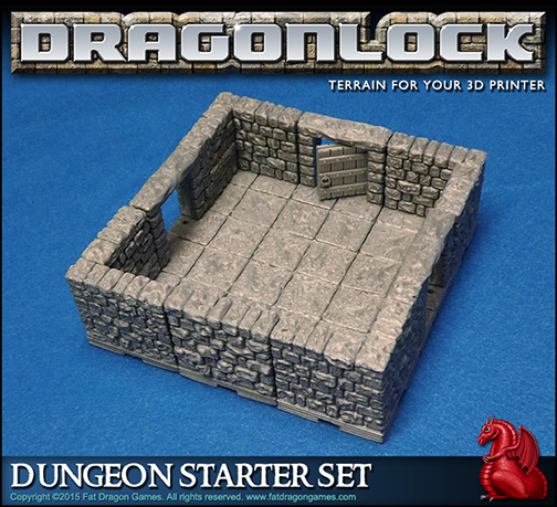