This is pleasingly weird.
https://www.dropbox.com/sh/sif3efs69dxe1mg/AACY0RJGXl4k8CVvauUbJtYFa?dl=0
Sort of a baseline-boosted multi-auto-transformer voltage-doubler
flyback.
What's strange is that adding the two snubbers increases the LT spice
sim speed radically, about 10:1.
On 9/24/2023 12:18 PM, John Larkin wrote:
This is pleasingly weird.
https://www.dropbox.com/sh/sif3efs69dxe1mg/AACY0RJGXl4k8CVvauUbJtYFa?dl=0
Sort of a baseline-boosted multi-auto-transformer voltage-doubler
flyback.
There are bunch of topologies that charge inductors in parallel and
discharge in series, helps take the stress off the switch(es) and don't
need huge duty cycles. I have one like that in my filez that's like a
Cuk, with a quasi-floating output posted at the end though haven't found
a particular use for it yet..
What's strange is that adding the two snubbers increases the LT spice
sim speed radically, about 10:1.
High dv/dt stiffens the system, maybe.
Version 4
SHEET 1 2640 1316
WIRE 16 -768 -912 -768
WIRE 448 -768 16 -768
WIRE 672 -768 448 -768
WIRE 16 -624 16 -768
WIRE 448 -624 448 -768
WIRE 672 -400 672 -768
WIRE 224 -384 -624 -384
WIRE 448 -384 448 -544
WIRE 448 -384 304 -384
WIRE 512 -384 448 -384
WIRE 624 -384 576 -384
WIRE 16 -208 16 -544
WIRE 976 -208 16 -208
WIRE 1200 -208 976 -208
WIRE 1488 -208 1264 -208
WIRE 1728 -208 1488 -208
WIRE 2032 -208 1808 -208
WIRE 2432 -208 2032 -208
WIRE 2528 -208 2432 -208
WIRE -624 -80 -624 -384
WIRE 976 -64 976 -208
WIRE 1488 -64 1488 -208
WIRE 2432 64 2432 -208
WIRE -912 80 -912 -768
WIRE 976 80 976 0
WIRE 1488 80 1488 0
WIRE 2032 80 2032 -208
WIRE 16 288 16 -208
WIRE -624 368 -624 -16
WIRE -528 368 -624 368
WIRE -384 368 -448 368
WIRE -144 368 -384 368
WIRE -32 368 -80 368
WIRE 672 368 672 -304
WIRE 976 368 1488 80
WIRE 976 368 672 368
WIRE 1216 368 976 368
WIRE 1504 368 976 80
WIRE 1504 368 1280 368
WIRE 2032 368 2032 144
WIRE 2032 368 1504 368
WIRE 2432 368 2432 144
WIRE 2432 368 2032 368
WIRE 2512 368 2432 368
WIRE 2432 480 2432 368
WIRE -384 512 -384 368
WIRE 672 608 672 368
WIRE 2432 624 2432 560
WIRE -912 800 -912 160
WIRE -384 800 -384 592
WIRE -384 800 -912 800
WIRE 16 800 16 384
WIRE 16 800 -384 800
WIRE 672 800 672 688
WIRE 672 800 16 800
WIRE 16 880 16 800
WIRE -624 912 -624 368
WIRE -624 1120 -624 992
FLAG 16 880 0
FLAG -624 1120 0
FLAG 2432 624 0
FLAG 2528 -208 Out-
IOPIN 2528 -208 Out
FLAG 2512 368 Out+
IOPIN 2512 368 Out
SYMBOL voltage -912 64 R0
WINDOW 123 0 0 Left 0
WINDOW 39 0 0 Left 0
SYMATTR InstName V1
SYMATTR Value 5
SYMBOL nmos -32 288 R0
SYMATTR InstName M1
SYMATTR Value Si3440DV
SYMBOL cap 1264 -224 R90
WINDOW 0 0 32 VBottom 2
WINDOW 3 40 32 VTop 2
SYMATTR InstName C1
SYMATTR Value 0.47�
SYMBOL cap 1280 352 R90
WINDOW 0 0 32 VBottom 2
WINDOW 3 32 32 VTop 2
SYMATTR InstName C2
SYMATTR Value 0.47�
SYMBOL ind2 1712 -192 R270
WINDOW 0 32 56 VTop 2
WINDOW 3 4 56 VBottom 2
SYMATTR InstName L3
SYMATTR Value 220�
SYMBOL schottky 960 -64 R0
SYMATTR InstName D2
SYMATTR Value RB168LAM150
SYMATTR Description Diode
SYMATTR Type diode
SYMBOL voltage -624 896 R0
WINDOW 3 52 50 Left 2
WINDOW 123 0 0 Left 0
WINDOW 39 0 0 Left 0
SYMATTR Value PULSE(0 5 0 10n 10n 0.0000122 0.0000142)
SYMATTR InstName V2
SYMBOL cap 2016 80 R0
SYMATTR InstName C4
SYMATTR Value 4.7�
SYMBOL ind2 32 -528 R180
WINDOW 0 36 80 Left 2
WINDOW 3 36 40 Left 2
SYMATTR InstName L1
SYMATTR Value 220�
SYMBOL ind2 688 704 R180
WINDOW 0 36 80 Left 2
WINDOW 3 36 40 Left 2
SYMATTR InstName L2
SYMATTR Value 220�
SYMBOL res 2416 464 R0
SYMATTR InstName R1
SYMATTR Value 1Meg
SYMBOL Digital\\inv -688 -16 R270
SYMATTR InstName A1
SYMATTR SpiceLine Vhigh=5V,Td=5e-9,Trise=100n
SYMBOL pmos 624 -304 M180
SYMATTR InstName M2
SYMATTR Value QS8M51_P
SYMBOL ind2 208 -368 R270
WINDOW 0 32 56 VTop 2
WINDOW 3 4 56 VBottom 2
SYMATTR InstName L6
SYMATTR Value 2.2�
SYMBOL ind2 -544 384 R270
WINDOW 0 32 56 VTop 2
WINDOW 3 4 56 VBottom 2
SYMATTR InstName L7
SYMATTR Value 2.2�
SYMBOL res -400 496 R0
SYMATTR InstName R3
SYMATTR Value 10k
SYMBOL res 432 -640 R0
SYMATTR InstName R4
SYMATTR Value 10k
SYMBOL FerriteBead 544 -384 R90
WINDOW 0 -16 0 VBottom 2
SYMATTR InstName L4
SYMATTR Value 1.542�
SYMATTR SpiceLine Ipk=2 Rser=0.045 Rpar=587 Cpar=1.216p mfg="W�rth >Elektronik" pn="74279218 WE-CBF 1206"
SYMBOL res 2416 48 R0
SYMATTR InstName Rload
SYMATTR Value 10k
SYMBOL FerriteBead -112 368 R90
WINDOW 0 -16 0 VBottom 2
SYMATTR InstName L5
SYMATTR Value 1.542�
SYMATTR SpiceLine Ipk=2 Rser=0.045 Rpar=587 Cpar=1.216p mfg="W�rth >Elektronik" pn="74279218 WE-CBF 1206"
SYMBOL schottky 1472 -64 R0
SYMATTR InstName D1
SYMATTR Value RB168LAM150
SYMATTR Description Diode
SYMATTR Type diode
TEXT -872 560 Left 2 !.tran 0.1
TEXT 200 -568 Left 2 !K1 L1 L6 0.99
TEXT 256 464 Left 2 !K2 L7 L2 0.99
On Sun, 24 Sep 2023 12:38:28 -0400, bitrex <us...@example.net> wrote:
On 9/24/2023 12:18 PM, John Larkin wrote:
This is pleasingly weird.
https://www.dropbox.com/sh/sif3efs69dxe1mg/AACY0RJGXl4k8CVvauUbJtYFa?dl=0 >>
Sort of a baseline-boosted multi-auto-transformer voltage-doubler
flyback.
There are bunch of topologies that charge inductors in parallel and >discharge in series, helps take the stress off the switch(es) and don't >need huge duty cycles. I have one like that in my filez that's like a
Cuk, with a quasi-floating output posted at the end though haven't found
a particular use for it yet..
I started simulating with a single 1:5 transformer, but couldn't find
one for sale.
24 to 500 is sort of a black hole for flyback transformers. The
"capacitor charging" flybacks are either the wrong ratio or too wimpy.
On 9/24/2023 1:25 PM, John Larkin wrote:
On Sun, 24 Sep 2023 12:38:28 -0400, bitrex <user@example.net> wrote:
On 9/24/2023 12:18 PM, John Larkin wrote:
This is pleasingly weird.
https://www.dropbox.com/sh/sif3efs69dxe1mg/AACY0RJGXl4k8CVvauUbJtYFa?dl=0 >>>>
Sort of a baseline-boosted multi-auto-transformer voltage-doubler
flyback.
There are bunch of topologies that charge inductors in parallel and
discharge in series, helps take the stress off the switch(es) and don't
need huge duty cycles. I have one like that in my filez that's like a
Cuk, with a quasi-floating output posted at the end though haven't found >>> a particular use for it yet..
I started simulating with a single 1:5 transformer, but couldn't find
one for sale.
24 to 500 is sort of a black hole for flyback transformers. The
"capacitor charging" flybacks are either the wrong ratio or too wimpy.
The DRQ127 parts are cool and cheap (under a dollar) and multi-sourced
and pick-and-place compatible, so it makes sense to use four of them.
Inductors charged in parallel and discharged in series does sound
cool, but I'd expect that to need a lot of parts.
If you have transformers with a dual secondary you can make a boosting >autotransformer-type topology by using the spare secondaries to couple >fluxes, so they act like they're all wound on the same core, sort of
like this somewhat silly example:
On Sun, 24 Sep 2023 12:38:28 -0400, bitrex <user@example.net> wrote:
On 9/24/2023 12:18 PM, John Larkin wrote:
This is pleasingly weird.
https://www.dropbox.com/sh/sif3efs69dxe1mg/AACY0RJGXl4k8CVvauUbJtYFa?dl=0 >>>
Sort of a baseline-boosted multi-auto-transformer voltage-doubler
flyback.
There are bunch of topologies that charge inductors in parallel and
discharge in series, helps take the stress off the switch(es) and don't
need huge duty cycles. I have one like that in my filez that's like a
Cuk, with a quasi-floating output posted at the end though haven't found
a particular use for it yet..
I started simulating with a single 1:5 transformer, but couldn't find
one for sale.
24 to 500 is sort of a black hole for flyback transformers. The
"capacitor charging" flybacks are either the wrong ratio or too wimpy.
The DRQ127 parts are cool and cheap (under a dollar) and multi-sourced
and pick-and-place compatible, so it makes sense to use four of them.
Inductors charged in parallel and discharged in series does sound
cool, but I'd expect that to need a lot of parts.
This is pleasingly weird.
https://www.dropbox.com/sh/sif3efs69dxe1mg/AACY0RJGXl4k8CVvauUbJtYFa?dl=0
Sort of a baseline-boosted multi-auto-transformer voltage-doubler
flyback.
What's strange is that adding the two snubbers increases the LT spice
sim speed radically, about 10:1.
I'm getting an efficiency of 66% from your graphs., meaning circuit is okay for low power. Where is all that loss coming from? Or going to more appropriately?
On Sunday, September 24, 2023 at 12:18:49?PM UTC-4, John Larkin wrote:
This is pleasingly weird.
https://www.dropbox.com/sh/sif3efs69dxe1mg/AACY0RJGXl4k8CVvauUbJtYFa?dl=0
Sort of a baseline-boosted multi-auto-transformer voltage-doubler
flyback.
It's an instance of a 25 year old (minimum) idea usually called a tapped inductor boost.
https://www.microsemi.com/document-portal/doc_view/124899-ips401-application-note
There are others, these people did the grunge work:
https://www.researchgate.net/figure/High-boost-topologies-a-Boost-flyback-topology-b-Tapped-inductor-boost-converter-c_fig2_273517256
You don't have to actually "join" to see the paper, they let you view/download.
source node.
What's strange is that adding the two snubbers increases the LT spice
sim speed radically, about 10:1.
That's because they're linearizing nodes that are difficult to handle with too much ideality like pure capacitances, inductances. How many times has LTS flipped out because it wants a finite conductance in parallel with a pure capacitance, usually to a
I'm getting an efficiency of 66% from your graphs., meaning circuit is okay for low power. Where is all that loss coming from? Or going to more appropriately?
On Sun, 24 Sep 2023 11:33:01 -0700 (PDT), Fred Bloggs <bloggs.fred...@gmail.com> wrote:
On Sunday, September 24, 2023 at 12:18:49?PM UTC-4, John Larkin wrote:
This is pleasingly weird.
https://www.dropbox.com/sh/sif3efs69dxe1mg/AACY0RJGXl4k8CVvauUbJtYFa?dl=0 >>
Sort of a baseline-boosted multi-auto-transformer voltage-doubler
flyback.
It's an instance of a 25 year old (minimum) idea usually called a tapped inductor boost.
https://www.microsemi.com/document-portal/doc_view/124899-ips401-application-note
There are others, these people did the grunge work:
https://www.researchgate.net/figure/High-boost-topologies-a-Boost-flyback-topology-b-Tapped-inductor-boost-converter-c_fig2_273517256
You don't have to actually "join" to see the paper, they let you view/download.
a source node.
What's strange is that adding the two snubbers increases the LT spice
sim speed radically, about 10:1.
That's because they're linearizing nodes that are difficult to handle with too much ideality like pure capacitances, inductances. How many times has LTS flipped out because it wants a finite conductance in parallel with a pure capacitance, usually to
The latest version seems to allow open caps and floating parts.
I'm getting an efficiency of 66% from your graphs., meaning circuit is okay for low power. Where is all that loss coming from? Or going to more appropriately?Resistors in the snubbers are burning watts. I'm seeing 90% without
the snubbers. They need tweaking. Their current virtue is to speed up
the sim time. Saveral other part values are there to do that, and will
be changed on the real thing.
At under 5 watts out, and megawatts available, I don't really need efficiency.
This is pleasingly weird.
https://www.dropbox.com/sh/sif3efs69dxe1mg/AACY0RJGXl4k8CVvauUbJtYFa?dl=0
Sort of a baseline-boosted multi-auto-transformer voltage-doubler
flyback.
What's strange is that adding the two snubbers increases the LT spice
sim speed radically, about 10:1.
On Sun, 24 Sep 2023 09:18:31 -0700, John Larkin <j...@997arbor.com>
wrote:
This is pleasingly weird.
https://www.dropbox.com/sh/sif3efs69dxe1mg/AACY0RJGXl4k8CVvauUbJtYFa?dl=0
Sort of a baseline-boosted multi-auto-transformer voltage-doubler
flyback.
What's strange is that adding the two snubbers increases the LT spiceLM5156 is a similar controller, but does spread-spectrum.
sim speed radically, about 10:1.
On Sunday, September 24, 2023 at 8:10:55?PM UTC-4, John Larkin wrote:
On Sun, 24 Sep 2023 09:18:31 -0700, John Larkin <j...@997arbor.com>
wrote:
LM5156 is a similar controller, but does spread-spectrum.
This is pleasingly weird.
https://www.dropbox.com/sh/sif3efs69dxe1mg/AACY0RJGXl4k8CVvauUbJtYFa?dl=0 >> >
Sort of a baseline-boosted multi-auto-transformer voltage-doubler
flyback.
What's strange is that adding the two snubbers increases the LT spice
sim speed radically, about 10:1.
Is that gimmick still in vogue? It's useful for powering up an RF synthesizer, but little else.
On Mon, 25 Sep 2023 08:44:34 -0700 (PDT), Fred Bloggs <bloggs.fred...@gmail.com> wrote:
On Sunday, September 24, 2023 at 8:10:55?PM UTC-4, John Larkin wrote:
On Sun, 24 Sep 2023 09:18:31 -0700, John Larkin <j...@997arbor.com>
wrote:
LM5156 is a similar controller, but does spread-spectrum.
This is pleasingly weird.
https://www.dropbox.com/sh/sif3efs69dxe1mg/AACY0RJGXl4k8CVvauUbJtYFa?dl=0
Sort of a baseline-boosted multi-auto-transformer voltage-doubler
flyback.
What's strange is that adding the two snubbers increases the LT spice
sim speed radically, about 10:1.
Is that gimmick still in vogue? It's useful for powering up an RF synthesizer, but little else.
It's for passing EMI tests.
https://www.dropbox.com/sh/8nd4dibu77znh44/AAAkO6lEHy9FZ50od2-mqt0va?dl=0
On Sun, 24 Sep 2023 13:41:12 -0400, bitrex <user@example.net> wrote:
On 9/24/2023 1:25 PM, John Larkin wrote:
On Sun, 24 Sep 2023 12:38:28 -0400, bitrex <user@example.net> wrote:
On 9/24/2023 12:18 PM, John Larkin wrote:
This is pleasingly weird.
https://www.dropbox.com/sh/sif3efs69dxe1mg/AACY0RJGXl4k8CVvauUbJtYFa?dl=0 >>>>>
Sort of a baseline-boosted multi-auto-transformer voltage-doubler
flyback.
There are bunch of topologies that charge inductors in parallel and
discharge in series, helps take the stress off the switch(es) and don't >>>> need huge duty cycles. I have one like that in my filez that's like a
Cuk, with a quasi-floating output posted at the end though haven't found >>>> a particular use for it yet..
I started simulating with a single 1:5 transformer, but couldn't find
one for sale.
24 to 500 is sort of a black hole for flyback transformers. The
"capacitor charging" flybacks are either the wrong ratio or too wimpy.
The DRQ127 parts are cool and cheap (under a dollar) and multi-sourced
and pick-and-place compatible, so it makes sense to use four of them.
Inductors charged in parallel and discharged in series does sound
cool, but I'd expect that to need a lot of parts.
I could also rectify each of my secondaries independently into DC, and
stack those in series. But no big benefit, more parts.
If you have transformers with a dual secondary you can make a boosting
autotransformer-type topology by using the spare secondaries to couple
fluxes, so they act like they're all wound on the same core, sort of
like this somewhat silly example:
The DRQ127's are 2 widings, 1:1. Handy parts.
What was your 3KV for? I'm powering a Pockels Cell driver. It's only a moderate number of KHz so I shouldn't need a lot of power.
It would be nice to spread-spectrum my supply. That LT chip is fixed
200 KHz. The customer can get whiney about EMI.
On 24/09/2023 6:59 pm, John Larkin wrote:
On Sun, 24 Sep 2023 13:41:12 -0400, bitrex <us...@example.net> wrote:
On 9/24/2023 1:25 PM, John Larkin wrote:
On Sun, 24 Sep 2023 12:38:28 -0400, bitrex <us...@example.net> wrote: >>>> On 9/24/2023 12:18 PM, John Larkin wrote:
Have you measured the inter-winding capacitance of those DRQ127s?
My guess is many tens of pF and if you simulate with that then your
snubber requirements may be quite changed?
On Tuesday, September 26, 2023 at 9:43:41 PM UTC+10, piglet wrote:inter-winding capacitance isn't excited so it's a clean measurement. A capacitance meter can give your the interwinding capacitance, if you keep the test frequency well below the self-resonant frequency.
On 24/09/2023 6:59 pm, John Larkin wrote:<snip>
On Sun, 24 Sep 2023 13:41:12 -0400, bitrex <us...@example.net> wrote:
On 9/24/2023 1:25 PM, John Larkin wrote:
On Sun, 24 Sep 2023 12:38:28 -0400, bitrex <us...@example.net> wrote: >>>> On 9/24/2023 12:18 PM, John Larkin wrote:
Have you measured the inter-winding capacitance of those DRQ127s?
My guess is many tens of pF and if you simulate with that then your snubber requirements may be quite changed?LTSpice certainly lets you simulate with parallel and inter-winding capacitances.
Winding capacitance is easy enough to measure - you just need to resonate the winding with it's parallel capacitance. For 1:1 transformers like this you can put the two winding in parallel and measure the resonant frequency of the combination. The
I suppose if you excited two windings anti-parallel you would emphasis the interwinding capacitance, but I'd have to Spice it to get some feel for what you'd see.
It's curious that the data sheet doesn't give parallel and interwinding capacitances. Transformers are something of a cottage industry, and not all the people who make them know as much as they might.
--
Bill Sloman, Sydney
On Tuesday, September 26, 2023 at 8:27:05?AM UTC-4, Anthony William Sloman wrote:inter-winding capacitance isn't excited so it's a clean measurement. A capacitance meter can give your the interwinding capacitance, if you keep the test frequency well below the self-resonant frequency.
On Tuesday, September 26, 2023 at 9:43:41?PM UTC+10, piglet wrote:
On 24/09/2023 6:59 pm, John Larkin wrote:<snip>
On Sun, 24 Sep 2023 13:41:12 -0400, bitrex <us...@example.net> wrote:
On 9/24/2023 1:25 PM, John Larkin wrote:
On Sun, 24 Sep 2023 12:38:28 -0400, bitrex <us...@example.net> wrote: >> > >>>> On 9/24/2023 12:18 PM, John Larkin wrote:
Have you measured the inter-winding capacitance of those DRQ127s?LTSpice certainly lets you simulate with parallel and inter-winding capacitances.
My guess is many tens of pF and if you simulate with that then your
snubber requirements may be quite changed?
Winding capacitance is easy enough to measure - you just need to resonate the winding with it's parallel capacitance. For 1:1 transformers like this you can put the two winding in parallel and measure the resonant frequency of the combination. The
technique of using a transistor, or any other switch, to set up a constant DC current in the winding representative of operating conditions, and then switch it off and measure the resulting resonant oscillation. Observing the decay also tells you about
I suppose if you excited two windings anti-parallel you would emphasis the interwinding capacitance, but I'd have to Spice it to get some feel for what you'd see.
It's curious that the data sheet doesn't give parallel and interwinding capacitances. Transformers are something of a cottage industry, and not all the people who make them know as much as they might.
He means what you would understand to be intrawinding capacitance, the sum total of capacitance in parallel with any specific winding. You're thinking of what would commonly be called winding coupling capacitance. Last time I measured it was by a
On 24/09/2023 6:59 pm, John Larkin wrote:
On Sun, 24 Sep 2023 13:41:12 -0400, bitrex <user@example.net> wrote:
On 9/24/2023 1:25 PM, John Larkin wrote:
On Sun, 24 Sep 2023 12:38:28 -0400, bitrex <user@example.net> wrote:
On 9/24/2023 12:18 PM, John Larkin wrote:
This is pleasingly weird.
https://www.dropbox.com/sh/sif3efs69dxe1mg/AACY0RJGXl4k8CVvauUbJtYFa?dl=0
Sort of a baseline-boosted multi-auto-transformer voltage-doubler
flyback.
There are bunch of topologies that charge inductors in parallel and
discharge in series, helps take the stress off the switch(es) and don't >>>>> need huge duty cycles. I have one like that in my filez that's like a >>>>> Cuk, with a quasi-floating output posted at the end though haven't found >>>>> a particular use for it yet..
I started simulating with a single 1:5 transformer, but couldn't find
one for sale.
24 to 500 is sort of a black hole for flyback transformers. The
"capacitor charging" flybacks are either the wrong ratio or too wimpy. >>>>
The DRQ127 parts are cool and cheap (under a dollar) and multi-sourced >>>> and pick-and-place compatible, so it makes sense to use four of them.
Inductors charged in parallel and discharged in series does sound
cool, but I'd expect that to need a lot of parts.
I could also rectify each of my secondaries independently into DC, and
stack those in series. But no big benefit, more parts.
If you have transformers with a dual secondary you can make a boosting
autotransformer-type topology by using the spare secondaries to couple
fluxes, so they act like they're all wound on the same core, sort of
like this somewhat silly example:
The DRQ127's are 2 widings, 1:1. Handy parts.
What was your 3KV for? I'm powering a Pockels Cell driver. It's only a
moderate number of KHz so I shouldn't need a lot of power.
It would be nice to spread-spectrum my supply. That LT chip is fixed
200 KHz. The customer can get whiney about EMI.
Have you measured the inter-winding capacitance of those DRQ127s?
My guess is many tens of pF and if you simulate with that then your
snubber requirements may be quite changed?
piglet
On Tuesday, September 26, 2023 at 8:27:05 AM UTC-4, Anthony William Sloman wrote:inter-winding capacitance isn't excited so it's a clean measurement. A capacitance meter can give your the interwinding capacitance, if you keep the test frequency well below the self-resonant frequency.
On Tuesday, September 26, 2023 at 9:43:41 PM UTC+10, piglet wrote:
On 24/09/2023 6:59 pm, John Larkin wrote:<snip>
On Sun, 24 Sep 2023 13:41:12 -0400, bitrex <us...@example.net> wrote:
On 9/24/2023 1:25 PM, John Larkin wrote:
On Sun, 24 Sep 2023 12:38:28 -0400, bitrex <us...@example.net> wrote:
On 9/24/2023 12:18 PM, John Larkin wrote:
Have you measured the inter-winding capacitance of those DRQ127s?
My guess is many tens of pF and if you simulate with that then your snubber requirements may be quite changed?LTSpice certainly lets you simulate with parallel and inter-winding capacitances.
Winding capacitance is easy enough to measure - you just need to resonate the winding with it's parallel capacitance. For 1:1 transformers like this you can put the two winding in parallel and measure the resonant frequency of the combination. The
I suppose if you excited two windings anti-parallel you would emphasis the interwinding capacitance, but I'd have to Spice it to get some feel for what you'd see.
It's curious that the data sheet doesn't give parallel and interwinding capacitances. Transformers are something of a cottage industry, and not all the people who make them know as much as they might.He means what you would understand to be intrawinding capacitance, the sum total of capacitance in parallel with any specific winding.
You're thinking of what would commonly be called winding coupling capacitance.
Last time I measured it was by a technique of using a transistor, or any other switch, to set up a constant DC current in the winding representative of operating conditions, and then switch it off and measure the resulting resonant oscillation.Observing the decay also tells you about the Q, or lack thereof due to core and winding loss.
On 24/09/2023 6:59 pm, John Larkin wrote:
On Sun, 24 Sep 2023 13:41:12 -0400, bitrex <user@example.net> wrote:
On 9/24/2023 1:25 PM, John Larkin wrote:
On Sun, 24 Sep 2023 12:38:28 -0400, bitrex <user@example.net> wrote:
On 9/24/2023 12:18 PM, John Larkin wrote:
This is pleasingly weird.
https://www.dropbox.com/sh/sif3efs69dxe1mg/AACY0RJGXl4k8CVvauUbJtYFa?dl=0
Sort of a baseline-boosted multi-auto-transformer voltage-doubler
flyback.
There are bunch of topologies that charge inductors in parallel and
discharge in series, helps take the stress off the switch(es) and don't >>>>> need huge duty cycles. I have one like that in my filez that's like a >>>>> Cuk, with a quasi-floating output posted at the end though haven't found >>>>> a particular use for it yet..
I started simulating with a single 1:5 transformer, but couldn't find
one for sale.
24 to 500 is sort of a black hole for flyback transformers. The
"capacitor charging" flybacks are either the wrong ratio or too wimpy. >>>>
The DRQ127 parts are cool and cheap (under a dollar) and multi-sourced >>>> and pick-and-place compatible, so it makes sense to use four of them.
Inductors charged in parallel and discharged in series does sound
cool, but I'd expect that to need a lot of parts.
I could also rectify each of my secondaries independently into DC, and
stack those in series. But no big benefit, more parts.
If you have transformers with a dual secondary you can make a boosting
autotransformer-type topology by using the spare secondaries to couple
fluxes, so they act like they're all wound on the same core, sort of
like this somewhat silly example:
The DRQ127's are 2 widings, 1:1. Handy parts.
What was your 3KV for? I'm powering a Pockels Cell driver. It's only a
moderate number of KHz so I shouldn't need a lot of power.
It would be nice to spread-spectrum my supply. That LT chip is fixed
200 KHz. The customer can get whiney about EMI.
Have you measured the inter-winding capacitance of those DRQ127s?
My guess is many tens of pF and if you simulate with that then your
snubber requirements may be quite changed?
piglet
I'm not sure how to Spice a distributed capacitance. Maybe put half on
each end?
This is pleasingly weird.
https://www.dropbox.com/sh/sif3efs69dxe1mg/AACY0RJGXl4k8CVvauUbJtYFa?dl=0
Sort of a baseline-boosted multi-auto-transformer voltage-doubler
flyback.
What's strange is that adding the two snubbers increases the LT spice
sim speed radically, about 10:1.
On Tue, 26 Sep 2023 12:43:30 +0100, piglet <erichp...@hotmail.com>
wrote:
On 24/09/2023 6:59 pm, John Larkin wrote:
On Sun, 24 Sep 2023 13:41:12 -0400, bitrex <us...@example.net> wrote:
On 9/24/2023 1:25 PM, John Larkin wrote:
On Sun, 24 Sep 2023 12:38:28 -0400, bitrex <us...@example.net> wrote: >>>>> On 9/24/2023 12:18 PM, John Larkin wrote:
Have you measured the inter-winding capacitance of those DRQ127s?
My guess is many tens of pF and if you simulate with that then your >snubber requirements may be quite changed?
pigletDRQ127, the big one in the DRQ family:
33 uH is 106 pF measuring two shorted windings
1 mH is 432 pF
I'm not sure how to Spice a distributed capacitance. Maybe put half on each end?
On Sun, 24 Sep 2023 09:18:31 -0700, John Larkin <jl@997arbor.com>
wrote:
This is pleasingly weird.
https://www.dropbox.com/sh/sif3efs69dxe1mg/AACY0RJGXl4k8CVvauUbJtYFa?dl=0
Sort of a baseline-boosted multi-auto-transformer voltage-doubler
flyback.
What's strange is that adding the two snubbers increases the LT spice
sim speed radically, about 10:1.
Since I couldn't find a suitable flyback transformer, and I only need
500 volts at 10 mA, a flyback/C-W multiplier makes sense.
https://www.dropbox.com/scl/fi/aquzpawfn8mfmfsnx70ra/T875_HV_6.jpg?rlkey=vfs9pexa0rgyxpo7pg1grqlb7&dl=0
On a sunny day (Tue, 26 Sep 2023 19:35:18 -0700) it happened John Larkin ><jl@997arbor.com> wrote in <mf47hi15db7eq7mp2nl9mdqgin7acrujdi@4ax.com>:
On Sun, 24 Sep 2023 09:18:31 -0700, John Larkin <jl@997arbor.com>
wrote:
This is pleasingly weird.
Sort of a baseline-boosted multi-auto-transformer voltage-doubler >>>flyback.https://www.dropbox.com/sh/sif3efs69dxe1mg/AACY0RJGXl4k8CVvauUbJtYFa?dl=0 >>>
What's strange is that adding the two snubbers increases the LT spice
sim speed radically, about 10:1.
Since I couldn't find a suitable flyback transformer, and I only need
500 volts at 10 mA, a flyback/C-W multiplier makes sense.
https://www.dropbox.com/scl/fi/aquzpawfn8mfmfsnx70ra/T875_HV_6.jpg?rlkey=vfs9pexa0rgyxpo7pg1grqlb7&dl=0
Do you still need C11 R8 in that circuit?
On Wed, 27 Sep 2023 05:14:49 GMT, Jan Panteltje <alien@comet.invalid>
wrote:
On a sunny day (Tue, 26 Sep 2023 19:35:18 -0700) it happened John Larkin >><jl@997arbor.com> wrote in <mf47hi15db7eq7mp2nl9mdqgin7acrujdi@4ax.com>:
On Sun, 24 Sep 2023 09:18:31 -0700, John Larkin <jl@997arbor.com>
wrote:
This is pleasingly weird.
Sort of a baseline-boosted multi-auto-transformer voltage-doubler >>>>flyback.https://www.dropbox.com/sh/sif3efs69dxe1mg/AACY0RJGXl4k8CVvauUbJtYFa?dl=0 >>>>
What's strange is that adding the two snubbers increases the LT spice >>>>sim speed radically, about 10:1.
Since I couldn't find a suitable flyback transformer, and I only need
500 volts at 10 mA, a flyback/C-W multiplier makes sense.
https://www.dropbox.com/scl/fi/aquzpawfn8mfmfsnx70ra/T875_HV_6.jpg?rlkey=vfs9pexa0rgyxpo7pg1grqlb7&dl=0
Do you still need C11 R8 in that circuit?
It doesn't need them to work, but there is a big high-Q ring when the
fet turns off, and the RC damps it. It would reduce radiated EMI. And
it speeds up the simulation some.
On a sunny day (Wed, 27 Sep 2023 00:51:10 -0700) it happened John Larkin ><jl@997arbor.com> wrote in <4bn7hit0n3rmcg8551cskijart3cnh9ess@4ax.com>:
On Wed, 27 Sep 2023 05:14:49 GMT, Jan Panteltje <alien@comet.invalid> >>wrote:
On a sunny day (Tue, 26 Sep 2023 19:35:18 -0700) it happened John Larkin >>><jl@997arbor.com> wrote in <mf47hi15db7eq7mp2nl9mdqgin7acrujdi@4ax.com>:
On Sun, 24 Sep 2023 09:18:31 -0700, John Larkin <jl@997arbor.com> >>>>wrote:
This is pleasingly weird.
Sort of a baseline-boosted multi-auto-transformer voltage-doubler >>>>>flyback.https://www.dropbox.com/sh/sif3efs69dxe1mg/AACY0RJGXl4k8CVvauUbJtYFa?dl=0 >>>>>
What's strange is that adding the two snubbers increases the LT spice >>>>>sim speed radically, about 10:1.
Since I couldn't find a suitable flyback transformer, and I only need >>>>500 volts at 10 mA, a flyback/C-W multiplier makes sense.
https://www.dropbox.com/scl/fi/aquzpawfn8mfmfsnx70ra/T875_HV_6.jpg?rlkey=vfs9pexa0rgyxpo7pg1grqlb7&dl=0
Do you still need C11 R8 in that circuit?
It doesn't need them to work, but there is a big high-Q ring when the
fet turns off, and the RC damps it. It would reduce radiated EMI. And
it speeds up the simulation some.
Did you scope that?
There is a load of capacitance hanging from the MOSFET drain in that flyback multiplier ciruit
I would expect it to damp RF oscillations but could be wrong...
HV diodes have capacitance too..
On Wed, 27 Sep 2023 11:44:57 GMT, Jan Panteltje <alien@comet.invalid>
wrote:
On a sunny day (Wed, 27 Sep 2023 00:51:10 -0700) it happened John Larkin >><jl@997arbor.com> wrote in <4bn7hit0n3rmcg8551cskijart3cnh9ess@4ax.com>:
On Wed, 27 Sep 2023 05:14:49 GMT, Jan Panteltje <alien@comet.invalid> >>>wrote:
On a sunny day (Tue, 26 Sep 2023 19:35:18 -0700) it happened John Larkin >>>><jl@997arbor.com> wrote in <mf47hi15db7eq7mp2nl9mdqgin7acrujdi@4ax.com>: >>>>
On Sun, 24 Sep 2023 09:18:31 -0700, John Larkin <jl@997arbor.com> >>>>>wrote:
This is pleasingly weird.
Sort of a baseline-boosted multi-auto-transformer voltage-doubler >>>>>>flyback.https://www.dropbox.com/sh/sif3efs69dxe1mg/AACY0RJGXl4k8CVvauUbJtYFa?dl=0 >>>>>>
What's strange is that adding the two snubbers increases the LT spice >>>>>>sim speed radically, about 10:1.
Since I couldn't find a suitable flyback transformer, and I only need >>>>>500 volts at 10 mA, a flyback/C-W multiplier makes sense.
https://www.dropbox.com/scl/fi/aquzpawfn8mfmfsnx70ra/T875_HV_6.jpg?rlkey=vfs9pexa0rgyxpo7pg1grqlb7&dl=0
Do you still need C11 R8 in that circuit?
It doesn't need them to work, but there is a big high-Q ring when the
fet turns off, and the RC damps it. It would reduce radiated EMI. And
it speeds up the simulation some.
Did you scope that?
All Spice now. I'll build it when the customer gets serious.
There is a load of capacitance hanging from the MOSFET drain in that flyback multiplier ciruit
I would expect it to damp RF oscillations but could be wrong...
HV diodes have capacitance too..
The real circuit will have a lot of inductances too, what with those
long strings of parts. It needs to be built and tested. Dremeled, to
start.
Here's an old auto-flyback C-W miltiplier prototype. I think that was
1400 volts. Worked fine.
https://www.dropbox.com/s/yd19osiwz1z74s4/HV_Proto_2.JPG?rsw=1
On a sunny day (Wed, 27 Sep 2023 08:10:02 -0700) it happened John Larkin <j...@997arbor.com> wrote in <d3h8hitm54oie4gcl...@4ax.com>:For my case, I am working on a 5W 24V to 4.5kV converter. Right now looking to use a flyback topology, with possibly usage of CCFL transformer bobbins.
On Wed, 27 Sep 2023 11:44:57 GMT, Jan Panteltje <al...@comet.invalid> >wrote:
On a sunny day (Wed, 27 Sep 2023 00:51:10 -0700) it happened John Larkin >><j...@997arbor.com> wrote in <4bn7hit0n3rmcg855...@4ax.com>:
On Wed, 27 Sep 2023 05:14:49 GMT, Jan Panteltje <al...@comet.invalid> >>>wrote:
On a sunny day (Tue, 26 Sep 2023 19:35:18 -0700) it happened John Larkin >>>><j...@997arbor.com> wrote in <mf47hi15db7eq7mp2...@4ax.com>:
On Sun, 24 Sep 2023 09:18:31 -0700, John Larkin <j...@997arbor.com> >>>>>wrote:
This is pleasingly weird.
https://www.dropbox.com/sh/sif3efs69dxe1mg/AACY0RJGXl4k8CVvauUbJtYFa?dl=0
Sort of a baseline-boosted multi-auto-transformer voltage-doubler >>>>>>flyback.
What's strange is that adding the two snubbers increases the LT spice >>>>>>sim speed radically, about 10:1.
Since I couldn't find a suitable flyback transformer, and I only need >>>>>500 volts at 10 mA, a flyback/C-W multiplier makes sense.
https://www.dropbox.com/scl/fi/aquzpawfn8mfmfsnx70ra/T875_HV_6.jpg?rlkey=vfs9pexa0rgyxpo7pg1grqlb7&dl=0
Do you still need C11 R8 in that circuit?
It doesn't need them to work, but there is a big high-Q ring when the >>>fet turns off, and the RC damps it. It would reduce radiated EMI. And >>>it speeds up the simulation some.
Did you scope that?
All Spice now. I'll build it when the customer gets serious.
There is a load of capacitance hanging from the MOSFET drain in that flyback multiplier ciruit
I would expect it to damp RF oscillations but could be wrong...
HV diodes have capacitance too..
The real circuit will have a lot of inductances too, what with those
long strings of parts. It needs to be built and tested. Dremeled, to
start.
Here's an old auto-flyback C-W miltiplier prototype. I think that was
1400 volts. Worked fine.
https://www.dropbox.com/s/yd19osiwz1z74s4/HV_Proto_2.JPG?rsw=1Yea,
I did a PMT supply this way: http://panteltje.nl/pub/PMT_HV_supply_with_regulator_img_3175.jpg http://panteltje.nl/pub/PMT_HV_supply_componet_side_img_3180.jpg http://panteltje.nl/pub/PMT_regulated_power_supply_diagram_img_3182.jpg
It has been in use now for many years, sits with PMT in the cardboard tube on the right, runs on batteries:
http://panteltje.nl/pub/gamma_soectrometer_IMG_4505.JPG
Of course that is very low power, but for a bit more power, and using a real TV muliplier:
https://panteltje.nl/panteltje/pic/sc_pic/
No dremeling, boards are OK when they work..
And old TV circuits.. if you want a few kV there was / is? plenty stuff to be found on ebay.
On Wednesday, 27 September 2023 at 17:38:35 UTC+2, Jan Panteltje wrote:
On a sunny day (Wed, 27 Sep 2023 08:10:02 -0700) it happened John LarkinFor my case, I am working on a 5W 24V to 4.5kV converter. Right now looking to use a flyback topology, with possibly usage of CCFL transformer bobbins.
<j...@997arbor.com> wrote in <d3h8hitm54oie4gcl...@4ax.com>:
On Wed, 27 Sep 2023 11:44:57 GMT, Jan Panteltje <al...@comet.invalid>Yea,
wrote:
On a sunny day (Wed, 27 Sep 2023 00:51:10 -0700) it happened John Larkin >> >><j...@997arbor.com> wrote in <4bn7hit0n3rmcg855...@4ax.com>:
On Wed, 27 Sep 2023 05:14:49 GMT, Jan Panteltje <al...@comet.invalid>
wrote:
On a sunny day (Tue, 26 Sep 2023 19:35:18 -0700) it happened John Larkin >> >>>><j...@997arbor.com> wrote in <mf47hi15db7eq7mp2...@4ax.com>:
On Sun, 24 Sep 2023 09:18:31 -0700, John Larkin <j...@997arbor.com>
wrote:
This is pleasingly weird.
https://www.dropbox.com/sh/sif3efs69dxe1mg/AACY0RJGXl4k8CVvauUbJtYFa?dl=0
Sort of a baseline-boosted multi-auto-transformer voltage-doubler
flyback.
What's strange is that adding the two snubbers increases the LT spice >> >>>>>>sim speed radically, about 10:1.
Since I couldn't find a suitable flyback transformer, and I only need >> >>>>>500 volts at 10 mA, a flyback/C-W multiplier makes sense.
https://www.dropbox.com/scl/fi/aquzpawfn8mfmfsnx70ra/T875_HV_6.jpg?rlkey=vfs9pexa0rgyxpo7pg1grqlb7&dl=0
Do you still need C11 R8 in that circuit?
It doesn't need them to work, but there is a big high-Q ring when the
fet turns off, and the RC damps it. It would reduce radiated EMI. And
it speeds up the simulation some.
Did you scope that?
All Spice now. I'll build it when the customer gets serious.
There is a load of capacitance hanging from the MOSFET drain in that flyback multiplier ciruit
I would expect it to damp RF oscillations but could be wrong...
HV diodes have capacitance too..
The real circuit will have a lot of inductances too, what with those
long strings of parts. It needs to be built and tested. Dremeled, to
start.
Here's an old auto-flyback C-W miltiplier prototype. I think that was
1400 volts. Worked fine.
https://www.dropbox.com/s/yd19osiwz1z74s4/HV_Proto_2.JPG?rsw=1
I did a PMT supply this way:
http://panteltje.nl/pub/PMT_HV_supply_with_regulator_img_3175.jpg
http://panteltje.nl/pub/PMT_HV_supply_componet_side_img_3180.jpg
http://panteltje.nl/pub/PMT_regulated_power_supply_diagram_img_3182.jpg
It has been in use now for many years, sits with PMT in the cardboard tube on the right, runs on batteries:
http://panteltje.nl/pub/gamma_soectrometer_IMG_4505.JPG
Of course that is very low power, but for a bit more power, and using a real TV muliplier:
https://panteltje.nl/panteltje/pic/sc_pic/
No dremeling, boards are OK when they work..
And old TV circuits.. if you want a few kV there was / is? plenty stuff to be found on ebay.
I am thinking about staggering the windings on 2 transformers, so the voltage across the windings will be lower, but still the individual transformer needs to handle 4.5kV insulation (functional, not safety)
Due to the limiting power, it could also be tempting to use the capacitive doublers as listed elsewhere in the thread
My worry goes beyond the design, also about corona effects, which comes into play at +kV voltages. Potting is surely needed.
On Wed, 27 Sep 2023 13:34:29 -0700 (PDT), Klaus Kragelund <klaus.k...@gmail.com> wrote:
For my case, I am working on a 5W 24V to 4.5kV converter. Right now looking to use a flyback topology, with possibly usage of CCFL transformer bobbins.
I am thinking about staggering the windings on 2 transformers, so the voltage across the windings will be lower, but still the individual transformer needs to handle 4.5kV insulation (functional, not safety)
Due to the limiting power, it could also be tempting to use the capacitive doublers as listed elsewhere in the thread
My worry goes beyond the design, also about corona effects, which comes into play at +kV voltages. Potting is surely needed.I'm doing 24 to 500, also about 5 watts.
The C-W multiplier has many virtues. You can use a more reasonable transformer, and lower voltage diodes and caps.
An actual CCFL transformer would work, if you can buy them. Turns
ratios are in the 50-100 sort of range.
Potting is ugly.
On Wednesday, 27 September 2023 at 17:38:35 UTC+2, Jan Panteltje wrote:
On a sunny day (Wed, 27 Sep 2023 08:10:02 -0700) it happened John LarkinFor my case, I am working on a 5W 24V to 4.5kV converter. Right now looking to use a flyback topology, with possibly usage of CCFL transformer bobbins.
<j...@997arbor.com> wrote in <d3h8hitm54oie4gcl...@4ax.com>:
On Wed, 27 Sep 2023 11:44:57 GMT, Jan Panteltje <al...@comet.invalid>Yea,
wrote:
On a sunny day (Wed, 27 Sep 2023 00:51:10 -0700) it happened John Larkin >> >><j...@997arbor.com> wrote in <4bn7hit0n3rmcg855...@4ax.com>:
On Wed, 27 Sep 2023 05:14:49 GMT, Jan Panteltje <al...@comet.invalid>
wrote:
On a sunny day (Tue, 26 Sep 2023 19:35:18 -0700) it happened John Larkin >> >>>><j...@997arbor.com> wrote in <mf47hi15db7eq7mp2...@4ax.com>:
On Sun, 24 Sep 2023 09:18:31 -0700, John Larkin <j...@997arbor.com>
wrote:
This is pleasingly weird.
https://www.dropbox.com/sh/sif3efs69dxe1mg/AACY0RJGXl4k8CVvauUbJtYFa?dl=0
Sort of a baseline-boosted multi-auto-transformer voltage-doubler
flyback.
What's strange is that adding the two snubbers increases the LT spice >> >>>>>>sim speed radically, about 10:1.
Since I couldn't find a suitable flyback transformer, and I only need >> >>>>>500 volts at 10 mA, a flyback/C-W multiplier makes sense.
https://www.dropbox.com/scl/fi/aquzpawfn8mfmfsnx70ra/T875_HV_6.jpg?rlkey=vfs9pexa0rgyxpo7pg1grqlb7&dl=0
Do you still need C11 R8 in that circuit?
It doesn't need them to work, but there is a big high-Q ring when the
fet turns off, and the RC damps it. It would reduce radiated EMI. And
it speeds up the simulation some.
Did you scope that?
All Spice now. I'll build it when the customer gets serious.
There is a load of capacitance hanging from the MOSFET drain in that flyback multiplier ciruit
I would expect it to damp RF oscillations but could be wrong...
HV diodes have capacitance too..
The real circuit will have a lot of inductances too, what with those
long strings of parts. It needs to be built and tested. Dremeled, to
start.
Here's an old auto-flyback C-W miltiplier prototype. I think that was
1400 volts. Worked fine.
https://www.dropbox.com/s/yd19osiwz1z74s4/HV_Proto_2.JPG?rsw=1
I did a PMT supply this way:
http://panteltje.nl/pub/PMT_HV_supply_with_regulator_img_3175.jpg
http://panteltje.nl/pub/PMT_HV_supply_componet_side_img_3180.jpg
http://panteltje.nl/pub/PMT_regulated_power_supply_diagram_img_3182.jpg
It has been in use now for many years, sits with PMT in the cardboard tube on the right, runs on batteries:
http://panteltje.nl/pub/gamma_soectrometer_IMG_4505.JPG
Of course that is very low power, but for a bit more power, and using a real TV muliplier:
https://panteltje.nl/panteltje/pic/sc_pic/
No dremeling, boards are OK when they work..
And old TV circuits.. if you want a few kV there was / is? plenty stuff to be found on ebay.
I am thinking about staggering the windings on 2 transformers, so the voltage across the windings will be lower, but still the individual transformer needs to handle 4.5kV insulation (functional, not safety)
Due to the limiting power, it could also be tempting to use the capacitive doublers as listed elsewhere in the thread
My worry goes beyond the design, also about corona effects, which comes into play at +kV voltages. Potting is surely needed.
On Wednesday, 27 September 2023 at 17:38:35 UTC+2, Jan Panteltje wrote:
On a sunny day (Wed, 27 Sep 2023 08:10:02 -0700) it happened John LarkinFor my case, I am working on a 5W 24V to 4.5kV converter. Right now looking to use a flyback topology, with possibly usage of
<j...@997arbor.com> wrote in <d3h8hitm54oie4gcl...@4ax.com>:
On Wed, 27 Sep 2023 11:44:57 GMT, Jan Panteltje <al...@comet.invalid>Yea,
wrote:
On a sunny day (Wed, 27 Sep 2023 00:51:10 -0700) it happened John Larkin >> >><j...@997arbor.com> wrote in <4bn7hit0n3rmcg855...@4ax.com>:
On Wed, 27 Sep 2023 05:14:49 GMT, Jan Panteltje <al...@comet.invalid>
wrote:
On a sunny day (Tue, 26 Sep 2023 19:35:18 -0700) it happened John Larkin >> >>>><j...@997arbor.com> wrote in <mf47hi15db7eq7mp2...@4ax.com>:
On Sun, 24 Sep 2023 09:18:31 -0700, John Larkin <j...@997arbor.com>
wrote:
This is pleasingly weird.
https://www.dropbox.com/sh/sif3efs69dxe1mg/AACY0RJGXl4k8CVvauUbJtYFa?dl=0
Sort of a baseline-boosted multi-auto-transformer voltage-doubler
flyback.
What's strange is that adding the two snubbers increases the LT spice >> >>>>>>sim speed radically, about 10:1.
Since I couldn't find a suitable flyback transformer, and I only need >> >>>>>500 volts at 10 mA, a flyback/C-W multiplier makes sense.
https://www.dropbox.com/scl/fi/aquzpawfn8mfmfsnx70ra/T875_HV_6.jpg?rlkey=vfs9pexa0rgyxpo7pg1grqlb7&dl=0
Do you still need C11 R8 in that circuit?
It doesn't need them to work, but there is a big high-Q ring when the
fet turns off, and the RC damps it. It would reduce radiated EMI. And
it speeds up the simulation some.
Did you scope that?
All Spice now. I'll build it when the customer gets serious.
There is a load of capacitance hanging from the MOSFET drain in that flyback multiplier ciruit
I would expect it to damp RF oscillations but could be wrong...
HV diodes have capacitance too..
The real circuit will have a lot of inductances too, what with those
long strings of parts. It needs to be built and tested. Dremeled, to
start.
Here's an old auto-flyback C-W miltiplier prototype. I think that was
1400 volts. Worked fine.
https://www.dropbox.com/s/yd19osiwz1z74s4/HV_Proto_2.JPG?rsw=1
I did a PMT supply this way:
http://panteltje.nl/pub/PMT_HV_supply_with_regulator_img_3175.jpg
http://panteltje.nl/pub/PMT_HV_supply_componet_side_img_3180.jpg
http://panteltje.nl/pub/PMT_regulated_power_supply_diagram_img_3182.jpg
It has been in use now for many years, sits with PMT in the cardboard tube on the right, runs on batteries:
http://panteltje.nl/pub/gamma_soectrometer_IMG_4505.JPG
Of course that is very low power, but for a bit more power, and using a real TV muliplier:
https://panteltje.nl/panteltje/pic/sc_pic/
No dremeling, boards are OK when they work..
And old TV circuits.. if you want a few kV there was / is? plenty stuff to be found on ebay.
CCFL transformer bobbins.
I am thinking about staggering the windings on 2 transformers, so the voltage across the windings will be lower, but still the
individual transformer needs to handle 4.5kV insulation (functional, not safety)
Due to the limiting power, it could also be tempting to use the capacitive doublers as listed elsewhere in the thread
My worry goes beyond the design, also about corona effects, which comes into play at +kV voltages. Potting is surely needed.
On a sunny day (Wed, 27 Sep 2023 13:34:29 -0700 (PDT)) it happened Klaus >Kragelund <klaus.kragelund@gmail.com> wrote in ><903144ac-6642-4a3f-bb85-f9c8485eaf03n@googlegroups.com>:
On Wednesday, 27 September 2023 at 17:38:35 UTC+2, Jan Panteltje wrote:
On a sunny day (Wed, 27 Sep 2023 08:10:02 -0700) it happened John Larkin >>> <j...@997arbor.com> wrote in <d3h8hitm54oie4gcl...@4ax.com>:For my case, I am working on a 5W 24V to 4.5kV converter. Right now looking to use a flyback topology, with possibly usage of
On Wed, 27 Sep 2023 11:44:57 GMT, Jan Panteltje <al...@comet.invalid>Yea,
wrote:
On a sunny day (Wed, 27 Sep 2023 00:51:10 -0700) it happened John Larkin >>> >><j...@997arbor.com> wrote in <4bn7hit0n3rmcg855...@4ax.com>:
On Wed, 27 Sep 2023 05:14:49 GMT, Jan Panteltje <al...@comet.invalid> >>> >>>wrote:
On a sunny day (Tue, 26 Sep 2023 19:35:18 -0700) it happened John Larkin
<j...@997arbor.com> wrote in <mf47hi15db7eq7mp2...@4ax.com>:
On Sun, 24 Sep 2023 09:18:31 -0700, John Larkin <j...@997arbor.com> >>> >>>>>wrote:
This is pleasingly weird.
https://www.dropbox.com/sh/sif3efs69dxe1mg/AACY0RJGXl4k8CVvauUbJtYFa?dl=0
Sort of a baseline-boosted multi-auto-transformer voltage-doubler
flyback.
What's strange is that adding the two snubbers increases the LT spice >>> >>>>>>sim speed radically, about 10:1.
Since I couldn't find a suitable flyback transformer, and I only need >>> >>>>>500 volts at 10 mA, a flyback/C-W multiplier makes sense.
https://www.dropbox.com/scl/fi/aquzpawfn8mfmfsnx70ra/T875_HV_6.jpg?rlkey=vfs9pexa0rgyxpo7pg1grqlb7&dl=0
Do you still need C11 R8 in that circuit?
It doesn't need them to work, but there is a big high-Q ring when the >>> >>>fet turns off, and the RC damps it. It would reduce radiated EMI. And >>> >>>it speeds up the simulation some.
Did you scope that?
All Spice now. I'll build it when the customer gets serious.
There is a load of capacitance hanging from the MOSFET drain in that flyback multiplier ciruit
I would expect it to damp RF oscillations but could be wrong...
HV diodes have capacitance too..
The real circuit will have a lot of inductances too, what with those
long strings of parts. It needs to be built and tested. Dremeled, to
start.
Here's an old auto-flyback C-W miltiplier prototype. I think that was
1400 volts. Worked fine.
https://www.dropbox.com/s/yd19osiwz1z74s4/HV_Proto_2.JPG?rsw=1
I did a PMT supply this way:
http://panteltje.nl/pub/PMT_HV_supply_with_regulator_img_3175.jpg
http://panteltje.nl/pub/PMT_HV_supply_componet_side_img_3180.jpg
http://panteltje.nl/pub/PMT_regulated_power_supply_diagram_img_3182.jpg
It has been in use now for many years, sits with PMT in the cardboard tube on the right, runs on batteries:
http://panteltje.nl/pub/gamma_soectrometer_IMG_4505.JPG
Of course that is very low power, but for a bit more power, and using a real TV muliplier:
https://panteltje.nl/panteltje/pic/sc_pic/
No dremeling, boards are OK when they work..
And old TV circuits.. if you want a few kV there was / is? plenty stuff to be found on ebay.
CCFL transformer bobbins.
I am thinking about staggering the windings on 2 transformers, so the voltage across the windings will be lower, but still the
individual transformer needs to handle 4.5kV insulation (functional, not safety)
Due to the limiting power, it could also be tempting to use the capacitive doublers as listed elsewhere in the thread
My worry goes beyond the design, also about corona effects, which comes into play at +kV voltages. Potting is surely needed.
For a HV transformer, old TV transformers (from the CRT times) may perhaps be an option:
https://www.google.com/search?client=firefox-b-e&q=ebay+horizonatl+TV+output+transformer
4.5 kV diodes were used for focus in color TV sets...
For a flyback, my rule of thumb (I do not use El Tea Spice), is 1 V per turn for DC input.
So 24 turns primary for 24 V DC supply.
The flyback voltage is (70/12) * 24 = 140V positive pulse if positive DC supply.
To get a 4.5 kV pulse you would then wind 4500 / 140 is about 32, multiplied by 24 makes 768 turns.
This for an EI core running at about 15 kHz (math comes from building TV output stages).
768 turns is not a big deal..
Spreading the turns over a segmented coil former is a good idea.
If you want to use a voltage multiplier then less turns are needed, use a TV multiplier, those are 'potted'
The 70/12 factor depends on the PWM on/off ratio of the drive you feed into the switch transistor.
I use Microchip PICs for that, it has a PWM unit., hardware comparators that can directly stop the PWM drive
for cycle by cycle current limiting, and ADCs to measure voltage and currents. >Maybe an old TV horizontal output transformer with build in rectifier / multiplier would do.
https://www.ebay.com/b/flyback-transformer/bn_7024744628
to adapt use 15 kHz and add 24 turns to the core primary?
...
:-)
Maybe like this?
https://www.ebay.com/p/1692562663?iid=374326473542
plenty space for 24 turns thick wire, its a 30 kV DC out, so use less PWM ... or more primary turns
or whatever you can find... on ebay.
On Thu, 28 Sep 2023 14:59:48 GMT, Jan Panteltje <al...@comet.invalidwrote: >On a sunny day (Wed, 27 Sep 2023 13:34:29 -0700 (PDT)) it happened Klaus Kragelund <klaus.k...@gmail.com> wrote in <903144ac-6642-4a3f...@googlegroups.com>:
On Wednesday, 27 September 2023 at 17:38:35 UTC+2, Jan Panteltje wrote: >>> On a sunny day (Wed, 27 Sep 2023 08:10:02 -0700) it happened John Larkin <j...@997arbor.com> wrote in <d3h8hitm54oie4gcl...@4ax.com>:
On Wed, 27 Sep 2023 11:44:57 GMT, Jan Panteltje <al...@comet.invalid> wrote:
On a sunny day (Wed, 27 Sep 2023 00:51:10 -0700) it happened John Larkin <j...@997arbor.com> wrote in <4bn7hit0n3rmcg855...@4ax.com>:
On Wed, 27 Sep 2023 05:14:49 GMT, Jan Panteltje <al...@comet.invalid> wrote:
On a sunny day (Tue, 26 Sep 2023 19:35:18 -0700) it happened John Larkin <j...@997arbor.com> wrote in <mf47hi15db7eq7mp2...@4ax.com>:
On Sun, 24 Sep 2023 09:18:31 -0700, John Larkin <j...@997arbor.com> wrote:
High turns ratios can have two problems: voltage breakdown in the insulation,
and winding capacitance limiting the flyback ratio.
That's where a C-W diode multiplier helps.
Old TV flybacks were pie wound to help with both problems. That makes a hand-wound transformer yet nastier; Sloman would love to (have someone else) wind that.
There are some cool old parts from CRT TVs but we wouldn't use Ebay parts for production. Even ISDN transformers are hard to get these days. And most of our boards have a component height limit below about 1".
I've gravitated to the classic C-W layout with all series strings of caps. That's driven by the poorly-or-never defined C/V behavior of available ceramic caps, which encourages their use at a small fractionof rated voltage.
There are lots of cute flyback controller chips that do peak current limiting control.
I don't know how much voltage we dare generate on a regular PCB without coating or potting. I'm guessing that 1KV is safe and I know that 7KV isn't.
On Wednesday, September 27, 2023 at 3:57:50?PM UTC-7, John Larkin wrote:
On Wed, 27 Sep 2023 13:34:29 -0700 (PDT), Klaus Kragelund
<klaus.k...@gmail.com> wrote:
For my case, I am working on a 5W 24V to 4.5kV converter. Right now looking to use a flyback topology, with possibly usage of CCFL transformer bobbins.I'm doing 24 to 500, also about 5 watts.
I am thinking about staggering the windings on 2 transformers, so the voltage across the windings will be lower, but still the individual transformer needs to handle 4.5kV insulation (functional, not safety)
Due to the limiting power, it could also be tempting to use the capacitive doublers as listed elsewhere in the thread
My worry goes beyond the design, also about corona effects, which comes into play at +kV voltages. Potting is surely needed.
The C-W multiplier has many virtues. You can use a more reasonable
transformer, and lower voltage diodes and caps.
An actual CCFL transformer would work, if you can buy them. Turns
ratios are in the 50-100 sort of range.
Potting is ugly.
Yeah, but it's compact and not messy.
On Wed, 27 Sep 2023 17:24:13 -0700 (PDT), whit3rd <whit3rd@gmail.com>
wrote:
On Wednesday, September 27, 2023 at 3:57:50?PM UTC-7, John Larkin wrote:
On Wed, 27 Sep 2023 13:34:29 -0700 (PDT), Klaus Kragelund
<klaus.k...@gmail.com> wrote:
For my case, I am working on a 5W 24V to 4.5kV converter. Right now looking to use a flyback topology, with possibly usage of CCFL transformer bobbins.I'm doing 24 to 500, also about 5 watts.
I am thinking about staggering the windings on 2 transformers, so the voltage across the windings will be lower, but still the individual transformer needs to handle 4.5kV insulation (functional, not safety)
Due to the limiting power, it could also be tempting to use the capacitive doublers as listed elsewhere in the thread
My worry goes beyond the design, also about corona effects, which comes into play at +kV voltages. Potting is surely needed.
The C-W multiplier has many virtues. You can use a more reasonable
transformer, and lower voltage diodes and caps.
An actual CCFL transformer would work, if you can buy them. Turns
ratios are in the 50-100 sort of range.
Potting is ugly.
Yeah, but it's compact and not messy.
It is very slow and expensive and messy. Buying the goo and a shell or
mold, mixing, degassing, pouring, curing, cleanup, and then you have a
thing that you can't probe or rework.
Globbing or coating is also a pain, but not as big a pain.
Expensive labor-intensive processes like potting and transformer
winding and exotic PCB fab seem to appeal to some people for some
strange reason.
On a sunny day (Wed, 27 Sep 2023 13:34:29 -0700 (PDT)) it happened Klaus Kragelund <klaus.k...@gmail.com> wrote in <903144ac-6642-4a3f...@googlegroups.com>:
On Wednesday, 27 September 2023 at 17:38:35 UTC+2, Jan Panteltje wrote:
On a sunny day (Wed, 27 Sep 2023 08:10:02 -0700) it happened John Larkin >> <j...@997arbor.com> wrote in <d3h8hitm54oie4gcl...@4ax.com>:For my case, I am working on a 5W 24V to 4.5kV converter. Right now looking to use a flyback topology, with possibly usage of
On Wed, 27 Sep 2023 11:44:57 GMT, Jan Panteltje <al...@comet.invalid>Yea,
wrote:
On a sunny day (Wed, 27 Sep 2023 00:51:10 -0700) it happened John Larkin >> >><j...@997arbor.com> wrote in <4bn7hit0n3rmcg855...@4ax.com>:
On Wed, 27 Sep 2023 05:14:49 GMT, Jan Panteltje <al...@comet.invalid> >> >>>wrote:
On a sunny day (Tue, 26 Sep 2023 19:35:18 -0700) it happened John Larkin
<j...@997arbor.com> wrote in <mf47hi15db7eq7mp2...@4ax.com>:
On Sun, 24 Sep 2023 09:18:31 -0700, John Larkin <j...@997arbor.com> >> >>>>>wrote:
This is pleasingly weird.
https://www.dropbox.com/sh/sif3efs69dxe1mg/AACY0RJGXl4k8CVvauUbJtYFa?dl=0
Sort of a baseline-boosted multi-auto-transformer voltage-doubler
flyback.
What's strange is that adding the two snubbers increases the LT spice
sim speed radically, about 10:1.
Since I couldn't find a suitable flyback transformer, and I only need >> >>>>>500 volts at 10 mA, a flyback/C-W multiplier makes sense.
https://www.dropbox.com/scl/fi/aquzpawfn8mfmfsnx70ra/T875_HV_6.jpg?rlkey=vfs9pexa0rgyxpo7pg1grqlb7&dl=0
Do you still need C11 R8 in that circuit?
It doesn't need them to work, but there is a big high-Q ring when the >> >>>fet turns off, and the RC damps it. It would reduce radiated EMI. And >> >>>it speeds up the simulation some.
Did you scope that?
All Spice now. I'll build it when the customer gets serious.
There is a load of capacitance hanging from the MOSFET drain in that flyback multiplier ciruit
I would expect it to damp RF oscillations but could be wrong...
HV diodes have capacitance too..
The real circuit will have a lot of inductances too, what with those
long strings of parts. It needs to be built and tested. Dremeled, to
start.
Here's an old auto-flyback C-W miltiplier prototype. I think that was
1400 volts. Worked fine.
https://www.dropbox.com/s/yd19osiwz1z74s4/HV_Proto_2.JPG?rsw=1
I did a PMT supply this way:
http://panteltje.nl/pub/PMT_HV_supply_with_regulator_img_3175.jpg
http://panteltje.nl/pub/PMT_HV_supply_componet_side_img_3180.jpg
http://panteltje.nl/pub/PMT_regulated_power_supply_diagram_img_3182.jpg
It has been in use now for many years, sits with PMT in the cardboard tube on the right, runs on batteries:
http://panteltje.nl/pub/gamma_soectrometer_IMG_4505.JPG
Of course that is very low power, but for a bit more power, and using a real TV muliplier:
https://panteltje.nl/panteltje/pic/sc_pic/
No dremeling, boards are OK when they work..
And old TV circuits.. if you want a few kV there was / is? plenty stuff to be found on ebay.
CCFL transformer bobbins.
I am thinking about staggering the windings on 2 transformers, so the voltage across the windings will be lower, but still the
individual transformer needs to handle 4.5kV insulation (functional, not safety)
Due to the limiting power, it could also be tempting to use the capacitive doublers as listed elsewhere in the thread
My worry goes beyond the design, also about corona effects, which comes into play at +kV voltages. Potting is surely needed.For a HV transformer, old TV transformers (from the CRT times) may perhaps be an option:
https://www.google.com/search?client=firefox-b-e&q=ebay+horizonatl+TV+output+transformer
4.5 kV diodes were used for focus in color TV sets...
For a flyback, my rule of thumb (I do not use El Tea Spice), is 1 V per turn for DC input.Yeah, 768 is not bad at all. A couple of months ago I did a E13 with 200 turns, no problem at all.
So 24 turns primary for 24 V DC supply.
The flyback voltage is (70/12) * 24 = 140V positive pulse if positive DC supply.
To get a 4.5 kV pulse you would then wind 4500 / 140 is about 32, multiplied by 24 makes 768 turns.
This for an EI core running at about 15 kHz (math comes from building TV output stages).
768 turns is not a big deal..
Spreading the turns over a segmented coil former is a good idea.Yes, that would handle the issue with large voltage differences on the secondary coil, and isolation to the primary
If you want to use a voltage multiplier then less turns are needed, use a TV multiplier, those are 'potted'Yeah, so that's a compromise between the voltage on the primary FET during energy delivery and optimum duty-cyle.
The 70/12 factor depends on the PWM on/off ratio of the drive you feed into the switch transistor.
I use Microchip PICs for that, it has a PWM unit., hardware comparators that can directly stop the PWM driveI use STM32s :-)
for cycle by cycle current limiting, and ADCs to measure voltage and currents.
Maybe an old TV horizontal output transformer with build in rectifier / multiplier would do.Would be interesting to see the internal construction of that one
https://www.ebay.com/b/flyback-transformer/bn_7024744628
to adapt use 15 kHz and add 24 turns to the core primary?
...
:-)
Maybe like this?
https://www.ebay.com/p/1692562663?iid=374326473542
plenty space for 24 turns thick wire, its a 30 kV DC out, so use less PWM ... or more primary turns
or whatever you can find... on ebay.
On Thu, 28 Sep 2023 14:59:48 GMT, Jan Panteltje <al...@comet.invalid>
wrote:
On a sunny day (Wed, 27 Sep 2023 13:34:29 -0700 (PDT)) it happened Klaus >Kragelund <klaus.k...@gmail.com> wrote in ><903144ac-6642-4a3f...@googlegroups.com>:
On Wednesday, 27 September 2023 at 17:38:35 UTC+2, Jan Panteltje wrote:
On a sunny day (Wed, 27 Sep 2023 08:10:02 -0700) it happened John Larkin >>> <j...@997arbor.com> wrote in <d3h8hitm54oie4gcl...@4ax.com>:For my case, I am working on a 5W 24V to 4.5kV converter. Right now looking to use a flyback topology, with possibly usage of
On Wed, 27 Sep 2023 11:44:57 GMT, Jan Panteltje <al...@comet.invalid> >>> >wrote:Yea,
On a sunny day (Wed, 27 Sep 2023 00:51:10 -0700) it happened John Larkin
<j...@997arbor.com> wrote in <4bn7hit0n3rmcg855...@4ax.com>:
On Wed, 27 Sep 2023 05:14:49 GMT, Jan Panteltje <al...@comet.invalid> >>> >>>wrote:
On a sunny day (Tue, 26 Sep 2023 19:35:18 -0700) it happened John Larkin
<j...@997arbor.com> wrote in <mf47hi15db7eq7mp2...@4ax.com>:
On Sun, 24 Sep 2023 09:18:31 -0700, John Larkin <j...@997arbor.com> >>> >>>>>wrote:
This is pleasingly weird.
https://www.dropbox.com/sh/sif3efs69dxe1mg/AACY0RJGXl4k8CVvauUbJtYFa?dl=0
Sort of a baseline-boosted multi-auto-transformer voltage-doubler >>> >>>>>>flyback.
What's strange is that adding the two snubbers increases the LT spice
sim speed radically, about 10:1.
Since I couldn't find a suitable flyback transformer, and I only need
500 volts at 10 mA, a flyback/C-W multiplier makes sense.
https://www.dropbox.com/scl/fi/aquzpawfn8mfmfsnx70ra/T875_HV_6.jpg?rlkey=vfs9pexa0rgyxpo7pg1grqlb7&dl=0
Do you still need C11 R8 in that circuit?
It doesn't need them to work, but there is a big high-Q ring when the >>> >>>fet turns off, and the RC damps it. It would reduce radiated EMI. And >>> >>>it speeds up the simulation some.
Did you scope that?
All Spice now. I'll build it when the customer gets serious.
There is a load of capacitance hanging from the MOSFET drain in that flyback multiplier ciruit
I would expect it to damp RF oscillations but could be wrong...
HV diodes have capacitance too..
The real circuit will have a lot of inductances too, what with those
long strings of parts. It needs to be built and tested. Dremeled, to
start.
Here's an old auto-flyback C-W miltiplier prototype. I think that was >>> >1400 volts. Worked fine.
https://www.dropbox.com/s/yd19osiwz1z74s4/HV_Proto_2.JPG?rsw=1
I did a PMT supply this way:
http://panteltje.nl/pub/PMT_HV_supply_with_regulator_img_3175.jpg
http://panteltje.nl/pub/PMT_HV_supply_componet_side_img_3180.jpg
http://panteltje.nl/pub/PMT_regulated_power_supply_diagram_img_3182.jpg >>>
It has been in use now for many years, sits with PMT in the cardboard tube on the right, runs on batteries:
http://panteltje.nl/pub/gamma_soectrometer_IMG_4505.JPG
Of course that is very low power, but for a bit more power, and using a real TV muliplier:
https://panteltje.nl/panteltje/pic/sc_pic/
No dremeling, boards are OK when they work..
And old TV circuits.. if you want a few kV there was / is? plenty stuff to be found on ebay.
CCFL transformer bobbins.
I am thinking about staggering the windings on 2 transformers, so the voltage across the windings will be lower, but still the
individual transformer needs to handle 4.5kV insulation (functional, not safety)
Due to the limiting power, it could also be tempting to use the capacitive doublers as listed elsewhere in the thread
My worry goes beyond the design, also about corona effects, which comes into play at +kV voltages. Potting is surely needed.
For a HV transformer, old TV transformers (from the CRT times) may perhaps be an option:
https://www.google.com/search?client=firefox-b-e&q=ebay+horizonatl+TV+output+transformer
4.5 kV diodes were used for focus in color TV sets...
For a flyback, my rule of thumb (I do not use El Tea Spice), is 1 V per turn for DC input.
So 24 turns primary for 24 V DC supply.
The flyback voltage is (70/12) * 24 = 140V positive pulse if positive DC supply.
To get a 4.5 kV pulse you would then wind 4500 / 140 is about 32, multiplied by 24 makes 768 turns.
This for an EI core running at about 15 kHz (math comes from building TV output stages).
768 turns is not a big deal..
Spreading the turns over a segmented coil former is a good idea.
If you want to use a voltage multiplier then less turns are needed, use a TV multiplier, those are 'potted'
The 70/12 factor depends on the PWM on/off ratio of the drive you feed into the switch transistor.
I use Microchip PICs for that, it has a PWM unit., hardware comparators that can directly stop the PWM drive
for cycle by cycle current limiting, and ADCs to measure voltage and currents.
Maybe an old TV horizontal output transformer with build in rectifier / multiplier would do.
https://www.ebay.com/b/flyback-transformer/bn_7024744628
to adapt use 15 kHz and add 24 turns to the core primary?
...
:-)
Maybe like this?
https://www.ebay.com/p/1692562663?iid=374326473542
plenty space for 24 turns thick wire, its a 30 kV DC out, so use less PWM ... or more primary turns
or whatever you can find... on ebay.
High turns ratios can have two problems: voltage breakdown in the
insulation, and winding capacitance limiting the flyback ratio. That's
where a C-W diode multiplier helps.
Old TV flybacks were pie wound to help with both problems. That makes
a hand-wound transformer yet nastier; Sloman would love to (have
someone else) wind that.
There are some cool old parts from CRT TVs but we wouldn't use Ebay
parts for production. Even ISDN transformers are hard to get these
days. And most of our boards have a component height limit below about
1".
I've gravitated to the classic C-W layout with all series strings of
caps. That's driven by the poorly-or-never defined C/V behavior of
available ceramic caps, which encourages their use at a small fraction
of rated voltage.
There are lots of cute flyback controller chips that do peak current
limiting control.
I don't know how much voltage we dare generate on a regular PCB
without coating or potting. I'm guessing that 1KV is safe and I know
that 7KV isn't.
On Thursday, 28 September 2023 at 17:26:46 UTC+2, John Larkin wrote:
On Thu, 28 Sep 2023 14:59:48 GMT, Jan Panteltje <al...@comet.invalid> wrote:
On a sunny day (Wed, 27 Sep 2023 13:34:29 -0700 (PDT)) it happened Klaus >Kragelund <klaus.k...@gmail.com> wrote in ><903144ac-6642-4a3f...@googlegroups.com>:
On Wednesday, 27 September 2023 at 17:38:35 UTC+2, Jan Panteltje wrote: >>> On a sunny day (Wed, 27 Sep 2023 08:10:02 -0700) it happened John Larkin
<j...@997arbor.com> wrote in <d3h8hitm54oie4gcl...@4ax.com>:For my case, I am working on a 5W 24V to 4.5kV converter. Right now looking to use a flyback topology, with possibly usage of
On Wed, 27 Sep 2023 11:44:57 GMT, Jan Panteltje <al...@comet.invalid> >>> >wrote:Yea,
On a sunny day (Wed, 27 Sep 2023 00:51:10 -0700) it happened John Larkin
<j...@997arbor.com> wrote in <4bn7hit0n3rmcg855...@4ax.com>:
On Wed, 27 Sep 2023 05:14:49 GMT, Jan Panteltje <al...@comet.invalid>
wrote:
On a sunny day (Tue, 26 Sep 2023 19:35:18 -0700) it happened John Larkin
<j...@997arbor.com> wrote in <mf47hi15db7eq7mp2...@4ax.com>:
On Sun, 24 Sep 2023 09:18:31 -0700, John Larkin <j...@997arbor.com>
wrote:
This is pleasingly weird.
https://www.dropbox.com/sh/sif3efs69dxe1mg/AACY0RJGXl4k8CVvauUbJtYFa?dl=0
Sort of a baseline-boosted multi-auto-transformer voltage-doubler >>> >>>>>>flyback.
What's strange is that adding the two snubbers increases the LT spice
sim speed radically, about 10:1.
Since I couldn't find a suitable flyback transformer, and I only need
500 volts at 10 mA, a flyback/C-W multiplier makes sense.
https://www.dropbox.com/scl/fi/aquzpawfn8mfmfsnx70ra/T875_HV_6.jpg?rlkey=vfs9pexa0rgyxpo7pg1grqlb7&dl=0
Do you still need C11 R8 in that circuit?
It doesn't need them to work, but there is a big high-Q ring when the
fet turns off, and the RC damps it. It would reduce radiated EMI. And
it speeds up the simulation some.
Did you scope that?
All Spice now. I'll build it when the customer gets serious.
There is a load of capacitance hanging from the MOSFET drain in that flyback multiplier ciruit
I would expect it to damp RF oscillations but could be wrong...
HV diodes have capacitance too..
The real circuit will have a lot of inductances too, what with those >>> >long strings of parts. It needs to be built and tested. Dremeled, to >>> >start.
Here's an old auto-flyback C-W miltiplier prototype. I think that was >>> >1400 volts. Worked fine.
https://www.dropbox.com/s/yd19osiwz1z74s4/HV_Proto_2.JPG?rsw=1
I did a PMT supply this way:
http://panteltje.nl/pub/PMT_HV_supply_with_regulator_img_3175.jpg
http://panteltje.nl/pub/PMT_HV_supply_componet_side_img_3180.jpg
http://panteltje.nl/pub/PMT_regulated_power_supply_diagram_img_3182.jpg >>>
It has been in use now for many years, sits with PMT in the cardboard tube on the right, runs on batteries:
http://panteltje.nl/pub/gamma_soectrometer_IMG_4505.JPG
Of course that is very low power, but for a bit more power, and using a real TV muliplier:
https://panteltje.nl/panteltje/pic/sc_pic/
No dremeling, boards are OK when they work..
And old TV circuits.. if you want a few kV there was / is? plenty stuff to be found on ebay.
CCFL transformer bobbins.
I am thinking about staggering the windings on 2 transformers, so the voltage across the windings will be lower, but still the
individual transformer needs to handle 4.5kV insulation (functional, not safety)
Due to the limiting power, it could also be tempting to use the capacitive doublers as listed elsewhere in the thread
My worry goes beyond the design, also about corona effects, which comes into play at +kV voltages. Potting is surely needed.
For a HV transformer, old TV transformers (from the CRT times) may perhaps be an option:
https://www.google.com/search?client=firefox-b-e&q=ebay+horizonatl+TV+output+transformer
4.5 kV diodes were used for focus in color TV sets...
For a flyback, my rule of thumb (I do not use El Tea Spice), is 1 V per turn for DC input.
So 24 turns primary for 24 V DC supply.
The flyback voltage is (70/12) * 24 = 140V positive pulse if positive DC supply.
To get a 4.5 kV pulse you would then wind 4500 / 140 is about 32, multiplied by 24 makes 768 turns.
This for an EI core running at about 15 kHz (math comes from building TV output stages).
768 turns is not a big deal..
Spreading the turns over a segmented coil former is a good idea.
If you want to use a voltage multiplier then less turns are needed, use a TV multiplier, those are 'potted'
The 70/12 factor depends on the PWM on/off ratio of the drive you feed into the switch transistor.
I use Microchip PICs for that, it has a PWM unit., hardware comparators that can directly stop the PWM drive
for cycle by cycle current limiting, and ADCs to measure voltage and currents.
Maybe an old TV horizontal output transformer with build in rectifier / multiplier would do.
https://www.ebay.com/b/flyback-transformer/bn_7024744628
to adapt use 15 kHz and add 24 turns to the core primary?
...
:-)
Maybe like this?
https://www.ebay.com/p/1692562663?iid=374326473542
plenty space for 24 turns thick wire, its a 30 kV DC out, so use less PWM ... or more primary turns
or whatever you can find... on ebay.
High turns ratios can have two problems: voltage breakdown in the insulation, and winding capacitance limiting the flyback ratio. That's where a C-W diode multiplier helps.I am driving a UV lamp, so I need to deliver a pulse. Possible with a multiplier, but doesn't make it easier
Old TV flybacks were pie wound to help with both problems. That makesPie wound, so that's adding on layers instead of across the bobbin?
a hand-wound transformer yet nastier; Sloman would love to (have
someone else) wind that.
There are some cool old parts from CRT TVs but we wouldn't use EbayI agree, Ebay does not work for production items :-)
parts for production. Even ISDN transformers are hard to get these
days. And most of our boards have a component height limit below about
1".
I've gravitated to the classic C-W layout with all series strings ofIn any case for the C-W multiplier to work properly, the charging of the caps needs to be kept low.
caps. That's driven by the poorly-or-never defined C/V behavior of available ceramic caps, which encourages their use at a small fraction
of rated voltage.
There are lots of cute flyback controller chips that do peak current limiting control.
I am using a microcontroller. Microcontroller and kV design does not sound good, right?
I don't know how much voltage we dare generate on a regular PCBPotting or conformal coating is probably needed to avoid carbonization of PCB surface.
without coating or potting. I'm guessing that 1KV is safe and I know
that 7KV isn't.
On Thursday, 28 September 2023 at 17:26:46 UTC+2, John Larkin wrote:
On Thu, 28 Sep 2023 14:59:48 GMT, Jan Panteltje <al...@comet.invalid>
wrote:
On a sunny day (Wed, 27 Sep 2023 13:34:29 -0700 (PDT)) it happened KlausHigh turns ratios can have two problems: voltage breakdown in the
Kragelund <klaus.k...@gmail.com> wrote in
<903144ac-6642-4a3f...@googlegroups.com>:
On Wednesday, 27 September 2023 at 17:38:35 UTC+2, Jan Panteltje wrote:
On a sunny day (Wed, 27 Sep 2023 08:10:02 -0700) it happened John Larkin >> >>> <j...@997arbor.com> wrote in <d3h8hitm54oie4gcl...@4ax.com>:For my case, I am working on a 5W 24V to 4.5kV converter. Right now looking to use a flyback topology, with possibly usage of
On Wed, 27 Sep 2023 11:44:57 GMT, Jan Panteltje <al...@comet.invalid> >> >>> >wrote:Yea,
On a sunny day (Wed, 27 Sep 2023 00:51:10 -0700) it happened John Larkin
<j...@997arbor.com> wrote in <4bn7hit0n3rmcg855...@4ax.com>:
On Wed, 27 Sep 2023 05:14:49 GMT, Jan Panteltje <al...@comet.invalid> >> >>> >>>wrote:
On a sunny day (Tue, 26 Sep 2023 19:35:18 -0700) it happened John Larkin
<j...@997arbor.com> wrote in <mf47hi15db7eq7mp2...@4ax.com>:
On Sun, 24 Sep 2023 09:18:31 -0700, John Larkin <j...@997arbor.com> >> >>> >>>>>wrote:
This is pleasingly weird.
https://www.dropbox.com/sh/sif3efs69dxe1mg/AACY0RJGXl4k8CVvauUbJtYFa?dl=0
Sort of a baseline-boosted multi-auto-transformer voltage-doubler >> >>> >>>>>>flyback.
What's strange is that adding the two snubbers increases the LT spice
sim speed radically, about 10:1.
Since I couldn't find a suitable flyback transformer, and I only need
500 volts at 10 mA, a flyback/C-W multiplier makes sense.
https://www.dropbox.com/scl/fi/aquzpawfn8mfmfsnx70ra/T875_HV_6.jpg?rlkey=vfs9pexa0rgyxpo7pg1grqlb7&dl=0
Do you still need C11 R8 in that circuit?
It doesn't need them to work, but there is a big high-Q ring when the >> >>> >>>fet turns off, and the RC damps it. It would reduce radiated EMI. And >> >>> >>>it speeds up the simulation some.
Did you scope that?
All Spice now. I'll build it when the customer gets serious.
There is a load of capacitance hanging from the MOSFET drain in that flyback multiplier ciruit
I would expect it to damp RF oscillations but could be wrong...
HV diodes have capacitance too..
The real circuit will have a lot of inductances too, what with those
long strings of parts. It needs to be built and tested. Dremeled, to
start.
Here's an old auto-flyback C-W miltiplier prototype. I think that was >> >>> >1400 volts. Worked fine.
https://www.dropbox.com/s/yd19osiwz1z74s4/HV_Proto_2.JPG?rsw=1
I did a PMT supply this way:
http://panteltje.nl/pub/PMT_HV_supply_with_regulator_img_3175.jpg
http://panteltje.nl/pub/PMT_HV_supply_componet_side_img_3180.jpg
http://panteltje.nl/pub/PMT_regulated_power_supply_diagram_img_3182.jpg >> >>>
It has been in use now for many years, sits with PMT in the cardboard tube on the right, runs on batteries:
http://panteltje.nl/pub/gamma_soectrometer_IMG_4505.JPG
Of course that is very low power, but for a bit more power, and using a real TV muliplier:
https://panteltje.nl/panteltje/pic/sc_pic/
No dremeling, boards are OK when they work..
And old TV circuits.. if you want a few kV there was / is? plenty stuff to be found on ebay.
CCFL transformer bobbins.
I am thinking about staggering the windings on 2 transformers, so the voltage across the windings will be lower, but still the
individual transformer needs to handle 4.5kV insulation (functional, not safety)
Due to the limiting power, it could also be tempting to use the capacitive doublers as listed elsewhere in the thread
My worry goes beyond the design, also about corona effects, which comes into play at +kV voltages. Potting is surely needed.
For a HV transformer, old TV transformers (from the CRT times) may perhaps be an option:
https://www.google.com/search?client=firefox-b-e&q=ebay+horizonatl+TV+output+transformer
4.5 kV diodes were used for focus in color TV sets...
For a flyback, my rule of thumb (I do not use El Tea Spice), is 1 V per turn for DC input.
So 24 turns primary for 24 V DC supply.
The flyback voltage is (70/12) * 24 = 140V positive pulse if positive DC supply.
To get a 4.5 kV pulse you would then wind 4500 / 140 is about 32, multiplied by 24 makes 768 turns.
This for an EI core running at about 15 kHz (math comes from building TV output stages).
768 turns is not a big deal..
Spreading the turns over a segmented coil former is a good idea.
If you want to use a voltage multiplier then less turns are needed, use a TV multiplier, those are 'potted'
The 70/12 factor depends on the PWM on/off ratio of the drive you feed into the switch transistor.
I use Microchip PICs for that, it has a PWM unit., hardware comparators that can directly stop the PWM drive
for cycle by cycle current limiting, and ADCs to measure voltage and currents.
Maybe an old TV horizontal output transformer with build in rectifier / multiplier would do.
https://www.ebay.com/b/flyback-transformer/bn_7024744628
to adapt use 15 kHz and add 24 turns to the core primary?
...
:-)
Maybe like this?
https://www.ebay.com/p/1692562663?iid=374326473542
plenty space for 24 turns thick wire, its a 30 kV DC out, so use less PWM ... or more primary turns
or whatever you can find... on ebay.
insulation, and winding capacitance limiting the flyback ratio. That's
where a C-W diode multiplier helps.
I am driving a UV lamp, so I need to deliver a pulse. Possible with a multiplier, but doesn't make it easier
Old TV flybacks were pie wound to help with both problems. That makes
a hand-wound transformer yet nastier; Sloman would love to (have
someone else) wind that.
Pie wound, so that's adding on layers instead of across the bobbin?
There are some cool old parts from CRT TVs but we wouldn't use Ebay
parts for production. Even ISDN transformers are hard to get these
days. And most of our boards have a component height limit below about
1".
I agree, Ebay does not work for production items :-)
I've gravitated to the classic C-W layout with all series strings of
caps. That's driven by the poorly-or-never defined C/V behavior of
available ceramic caps, which encourages their use at a small fraction
of rated voltage.
In any case for the C-W multiplier to work properly, the charging of the caps needs to be kept low.
I am using a microcontroller. Microcontroller and kV design does not sound good, right?
There are lots of cute flyback controller chips that do peak current
limiting control.
I don't know how much voltage we dare generate on a regular PCB
without coating or potting. I'm guessing that 1KV is safe and I know
that 7KV isn't.
Potting or conformal coating is probably needed to avoid carbonization of PCB surface.
On Wed, 27 Sep 2023 17:24:13 -0700 (PDT), whit3rd <whi...@gmail.com>
wrote:
On Wednesday, September 27, 2023 at 3:57:50?PM UTC-7, John Larkin wrote:
On Wed, 27 Sep 2023 13:34:29 -0700 (PDT), Klaus Kragelund
<klaus.k...@gmail.com> wrote:
Potting is ugly.
Yeah, but it's compact and not messy.
It is very slow and expensive and messy. Buying the goo and a shell or mold, mixing, degassing, pouring, curing, cleanup, and then you have a thing that you can't probe or rework.
Globbing or coating is also a pain, but not as big a pain.
Expensive labor-intensive processes like potting and transformer winding and exotic PCB fab seem to appeal to some people for some strange reason.
On Thursday, 28 September 2023 at 16:59:57 UTC+2, Jan Panteltje wrote:
On a sunny day (Wed, 27 Sep 2023 13:34:29 -0700 (PDT)) it happened KlausYeah, 768 is not bad at all. A couple of months ago I did a E13 with 200 turns, no problem at all.
Kragelund <klaus.k...@gmail.com> wrote in
<903144ac-6642-4a3f...@googlegroups.com>:
On Wednesday, 27 September 2023 at 17:38:35 UTC+2, Jan Panteltje wrote:For a HV transformer, old TV transformers (from the CRT times) may perhaps be an option:
On a sunny day (Wed, 27 Sep 2023 08:10:02 -0700) it happened John Larkin >> >> <j...@997arbor.com> wrote in <d3h8hitm54oie4gcl...@4ax.com>:For my case, I am working on a 5W 24V to 4.5kV converter. Right now looking to use a flyback topology, with possibly usage of
On Wed, 27 Sep 2023 11:44:57 GMT, Jan Panteltje <al...@comet.invalid>Yea,
wrote:
On a sunny day (Wed, 27 Sep 2023 00:51:10 -0700) it happened John Larkin
<j...@997arbor.com> wrote in <4bn7hit0n3rmcg855...@4ax.com>:
On Wed, 27 Sep 2023 05:14:49 GMT, Jan Panteltje <al...@comet.invalid> >> >> >>>wrote:
On a sunny day (Tue, 26 Sep 2023 19:35:18 -0700) it happened John Larkin
<j...@997arbor.com> wrote in <mf47hi15db7eq7mp2...@4ax.com>:
On Sun, 24 Sep 2023 09:18:31 -0700, John Larkin <j...@997arbor.com> >> >> >>>>>wrote:
This is pleasingly weird.
https://www.dropbox.com/sh/sif3efs69dxe1mg/AACY0RJGXl4k8CVvauUbJtYFa?dl=0
Sort of a baseline-boosted multi-auto-transformer voltage-doubler >> >> >>>>>>flyback.
What's strange is that adding the two snubbers increases the LT spice
sim speed radically, about 10:1.
Since I couldn't find a suitable flyback transformer, and I only need
500 volts at 10 mA, a flyback/C-W multiplier makes sense.
https://www.dropbox.com/scl/fi/aquzpawfn8mfmfsnx70ra/T875_HV_6.jpg?rlkey=vfs9pexa0rgyxpo7pg1grqlb7&dl=0
Do you still need C11 R8 in that circuit?
It doesn't need them to work, but there is a big high-Q ring when the >> >> >>>fet turns off, and the RC damps it. It would reduce radiated EMI. And >> >> >>>it speeds up the simulation some.
Did you scope that?
All Spice now. I'll build it when the customer gets serious.
There is a load of capacitance hanging from the MOSFET drain in that flyback multiplier ciruit
I would expect it to damp RF oscillations but could be wrong...
HV diodes have capacitance too..
The real circuit will have a lot of inductances too, what with those
long strings of parts. It needs to be built and tested. Dremeled, to
start.
Here's an old auto-flyback C-W miltiplier prototype. I think that was
1400 volts. Worked fine.
https://www.dropbox.com/s/yd19osiwz1z74s4/HV_Proto_2.JPG?rsw=1
I did a PMT supply this way:
http://panteltje.nl/pub/PMT_HV_supply_with_regulator_img_3175.jpg
http://panteltje.nl/pub/PMT_HV_supply_componet_side_img_3180.jpg
http://panteltje.nl/pub/PMT_regulated_power_supply_diagram_img_3182.jpg >> >>
It has been in use now for many years, sits with PMT in the cardboard tube on the right, runs on batteries:
http://panteltje.nl/pub/gamma_soectrometer_IMG_4505.JPG
Of course that is very low power, but for a bit more power, and using a real TV muliplier:
https://panteltje.nl/panteltje/pic/sc_pic/
No dremeling, boards are OK when they work..
And old TV circuits.. if you want a few kV there was / is? plenty stuff to be found on ebay.
CCFL transformer bobbins.
I am thinking about staggering the windings on 2 transformers, so the voltage across the windings will be lower, but still
the
individual transformer needs to handle 4.5kV insulation (functional, not safety)
Due to the limiting power, it could also be tempting to use the capacitive doublers as listed elsewhere in the thread
My worry goes beyond the design, also about corona effects, which comes into play at +kV voltages. Potting is surely needed.
https://www.google.com/search?client=firefox-b-e&q=ebay+horizonatl+TV+output+transformer
4.5 kV diodes were used for focus in color TV sets...
For a flyback, my rule of thumb (I do not use El Tea Spice), is 1 V per turn for DC input.
So 24 turns primary for 24 V DC supply.
The flyback voltage is (70/12) * 24 = 140V positive pulse if positive DC supply.
To get a 4.5 kV pulse you would then wind 4500 / 140 is about 32, multiplied by 24 makes 768 turns.
This for an EI core running at about 15 kHz (math comes from building TV output stages).
768 turns is not a big deal..
Spreading the turns over a segmented coil former is a good idea.Yes, that would handle the issue with large voltage differences on the secondary coil, and isolation to the primary
If you want to use a voltage multiplier then less turns are needed, use a TV multiplier, those are 'potted'Yeah, so that's a compromise between the voltage on the primary FET during energy delivery and optimum duty-cyle.
The 70/12 factor depends on the PWM on/off ratio of the drive you feed into the switch transistor.
I use Microchip PICs for that, it has a PWM unit., hardware comparators that can directly stop the PWM driveI use STM32s :-)
for cycle by cycle current limiting, and ADCs to measure voltage and currents.
Maybe an old TV horizontal output transformer with build in rectifier / multiplier would do.Would be interesting to see the internal construction of that one
https://www.ebay.com/b/flyback-transformer/bn_7024744628
to adapt use 15 kHz and add 24 turns to the core primary?
...
:-)
Maybe like this?
https://www.ebay.com/p/1692562663?iid=374326473542
plenty space for 24 turns thick wire, its a 30 kV DC out, so use less PWM ... or more primary turns
or whatever you can find... on ebay.
On Thursday, 28 September 2023 at 17:26:46 UTC+2, John Larkin wrote:
On Thu, 28 Sep 2023 14:59:48 GMT, Jan Panteltje <al...@comet.invalid> wrote:
On a sunny day (Wed, 27 Sep 2023 13:34:29 -0700 (PDT)) it happened Klaus >Kragelund <klaus.k...@gmail.com> wrote in ><903144ac-6642-4a3f...@googlegroups.com>:
On Wednesday, 27 September 2023 at 17:38:35 UTC+2, Jan Panteltje wrote: >>> On a sunny day (Wed, 27 Sep 2023 08:10:02 -0700) it happened John Larkin
<j...@997arbor.com> wrote in <d3h8hitm54oie4gcl...@4ax.com>:
On Wed, 27 Sep 2023 11:44:57 GMT, Jan Panteltje <al...@comet.invalid> >>> >wrote:
On a sunny day (Wed, 27 Sep 2023 00:51:10 -0700) it happened John Larkin
<j...@997arbor.com> wrote in <4bn7hit0n3rmcg855...@4ax.com>:
On Wed, 27 Sep 2023 05:14:49 GMT, Jan Panteltje <al...@comet.invalid>
wrote:
On a sunny day (Tue, 26 Sep 2023 19:35:18 -0700) it happened John Larkin
<j...@997arbor.com> wrote in <mf47hi15db7eq7mp2...@4ax.com>:
On Sun, 24 Sep 2023 09:18:31 -0700, John Larkin <j...@997arbor.com>
wrote:
High turns ratios can have two problems: voltage breakdown in the insulation, and winding capacitance limiting the flyback ratio. That's where a C-W diode multiplier helps.
I am driving a UV lamp, so I need to deliver a pulse. Possible with a multiplier, but doesn't make it easier.
Old TV flybacks were pie wound to help with both problems. That makes
a hand-wound transformer yet nastier; Sloman would love to (have
someone else) wind that.
Pie wound, so that's adding on layers instead of across the bobbin?
On Thu, 28 Sep 2023 13:58:40 -0700 (PDT), Klaus Kragelund <klaus.k...@gmail.com> wrote:
I am driving a UV lamp, so I need to deliver a pulse. Possible with a multiplier, but doesn't make it easierNo, the C-W multiplier isn't good for pulsing. Ixys has a 4700 volt
mosfet. A C-W multiplier could make the HV.
Maybe use a Marx generator? With medium-high voltage mos or SiC fets?
torsdag den 28. september 2023 kl. 22.58.46 UTC+2 skrev Klaus Kragelund:
On Thursday, 28 September 2023 at 17:26:46 UTC+2, John Larkin wrote:
On Thu, 28 Sep 2023 14:59:48 GMT, Jan Panteltje <al...@comet.invalid> wrote:
On a sunny day (Wed, 27 Sep 2023 13:34:29 -0700 (PDT)) it happened Klaus >Kragelund <klaus.k...@gmail.com> wrote in ><903144ac-6642-4a3f...@googlegroups.com>:
On Wednesday, 27 September 2023 at 17:38:35 UTC+2, Jan Panteltje wrote: >>> On a sunny day (Wed, 27 Sep 2023 08:10:02 -0700) it happened John Larkin
<j...@997arbor.com> wrote in <d3h8hitm54oie4gcl...@4ax.com>:For my case, I am working on a 5W 24V to 4.5kV converter. Right now looking to use a flyback topology, with possibly usage of
On Wed, 27 Sep 2023 11:44:57 GMT, Jan Panteltje <al...@comet.invalid>Yea,
wrote:
On a sunny day (Wed, 27 Sep 2023 00:51:10 -0700) it happened John Larkin
<j...@997arbor.com> wrote in <4bn7hit0n3rmcg855...@4ax.com>:
On Wed, 27 Sep 2023 05:14:49 GMT, Jan Panteltje <al...@comet.invalid>
wrote:
On a sunny day (Tue, 26 Sep 2023 19:35:18 -0700) it happened John Larkin
<j...@997arbor.com> wrote in <mf47hi15db7eq7mp2...@4ax.com>:
On Sun, 24 Sep 2023 09:18:31 -0700, John Larkin <j...@997arbor.com>
wrote:
This is pleasingly weird.
https://www.dropbox.com/sh/sif3efs69dxe1mg/AACY0RJGXl4k8CVvauUbJtYFa?dl=0
Sort of a baseline-boosted multi-auto-transformer voltage-doubler
flyback.
What's strange is that adding the two snubbers increases the LT spice
sim speed radically, about 10:1.
Since I couldn't find a suitable flyback transformer, and I only need
500 volts at 10 mA, a flyback/C-W multiplier makes sense.
https://www.dropbox.com/scl/fi/aquzpawfn8mfmfsnx70ra/T875_HV_6.jpg?rlkey=vfs9pexa0rgyxpo7pg1grqlb7&dl=0
Do you still need C11 R8 in that circuit?
It doesn't need them to work, but there is a big high-Q ring when the
fet turns off, and the RC damps it. It would reduce radiated EMI. And
it speeds up the simulation some.
Did you scope that?
All Spice now. I'll build it when the customer gets serious.
There is a load of capacitance hanging from the MOSFET drain in that flyback multiplier ciruit
I would expect it to damp RF oscillations but could be wrong...
HV diodes have capacitance too..
The real circuit will have a lot of inductances too, what with those >>> >long strings of parts. It needs to be built and tested. Dremeled, to >>> >start.
Here's an old auto-flyback C-W miltiplier prototype. I think that was
1400 volts. Worked fine.
https://www.dropbox.com/s/yd19osiwz1z74s4/HV_Proto_2.JPG?rsw=1
I did a PMT supply this way:
http://panteltje.nl/pub/PMT_HV_supply_with_regulator_img_3175.jpg
http://panteltje.nl/pub/PMT_HV_supply_componet_side_img_3180.jpg
http://panteltje.nl/pub/PMT_regulated_power_supply_diagram_img_3182.jpg
It has been in use now for many years, sits with PMT in the cardboard tube on the right, runs on batteries:
http://panteltje.nl/pub/gamma_soectrometer_IMG_4505.JPG
Of course that is very low power, but for a bit more power, and using a real TV muliplier:
https://panteltje.nl/panteltje/pic/sc_pic/
No dremeling, boards are OK when they work..
And old TV circuits.. if you want a few kV there was / is? plenty stuff to be found on ebay.
CCFL transformer bobbins.
I am thinking about staggering the windings on 2 transformers, so the voltage across the windings will be lower, but still the
individual transformer needs to handle 4.5kV insulation (functional, not safety)
Due to the limiting power, it could also be tempting to use the capacitive doublers as listed elsewhere in the thread
My worry goes beyond the design, also about corona effects, which comes into play at +kV voltages. Potting is surely needed.
For a HV transformer, old TV transformers (from the CRT times) may perhaps be an option:
https://www.google.com/search?client=firefox-b-e&q=ebay+horizonatl+TV+output+transformer
4.5 kV diodes were used for focus in color TV sets...
These are used for old style flash:For a flyback, my rule of thumb (I do not use El Tea Spice), is 1 V per turn for DC input.
So 24 turns primary for 24 V DC supply.
The flyback voltage is (70/12) * 24 = 140V positive pulse if positive DC supply.
To get a 4.5 kV pulse you would then wind 4500 / 140 is about 32, multiplied by 24 makes 768 turns.
This for an EI core running at about 15 kHz (math comes from building TV output stages).
768 turns is not a big deal..
Spreading the turns over a segmented coil former is a good idea.
If you want to use a voltage multiplier then less turns are needed, use a TV multiplier, those are 'potted'
The 70/12 factor depends on the PWM on/off ratio of the drive you feed into the switch transistor.
I use Microchip PICs for that, it has a PWM unit., hardware comparators that can directly stop the PWM drive
for cycle by cycle current limiting, and ADCs to measure voltage and currents.
Maybe an old TV horizontal output transformer with build in rectifier / multiplier would do.
https://www.ebay.com/b/flyback-transformer/bn_7024744628
to adapt use 15 kHz and add 24 turns to the core primary?
...
:-)
Maybe like this?
https://www.ebay.com/p/1692562663?iid=374326473542
plenty space for 24 turns thick wire, its a 30 kV DC out, so use less PWM ... or more primary turns
or whatever you can find... on ebay.
High turns ratios can have two problems: voltage breakdown in the insulation, and winding capacitance limiting the flyback ratio. That's where a C-W diode multiplier helps.I am driving a UV lamp, so I need to deliver a pulse. Possible with a multiplier, but doesn't make it easier
Old TV flybacks were pie wound to help with both problems. That makesPie wound, so that's adding on layers instead of across the bobbin?
a hand-wound transformer yet nastier; Sloman would love to (have
someone else) wind that.
There are some cool old parts from CRT TVs but we wouldn't use EbayI agree, Ebay does not work for production items :-)
parts for production. Even ISDN transformers are hard to get these
days. And most of our boards have a component height limit below about 1".
I've gravitated to the classic C-W layout with all series strings of caps. That's driven by the poorly-or-never defined C/V behavior of available ceramic caps, which encourages their use at a small fractionIn any case for the C-W multiplier to work properly, the charging of the caps needs to be kept low.
of rated voltage.
There are lots of cute flyback controller chips that do peak current limiting control.
I am using a microcontroller. Microcontroller and kV design does not sound good, right?how about something crazy, a car ignition coil? ratio about 1:100, isolation good for +20kV
I don't know how much voltage we dare generate on a regular PCBPotting or conformal coating is probably needed to avoid carbonization of PCB surface.
without coating or potting. I'm guessing that 1KV is safe and I know
that 7KV isn't.
coil-on-plug can be pretty small, if you need access to both ends of the secondary a dual output coil for wasted spark has that
On Thursday, 28 September 2023 at 23:09:44 UTC+2, Lasse Langwadt Christensen wrote:
torsdag den 28. september 2023 kl. 22.58.46 UTC+2 skrev Klaus Kragelund:These are used for old style flash:
On Thursday, 28 September 2023 at 17:26:46 UTC+2, John Larkin wrote:how about something crazy, a car ignition coil? ratio about 1:100, isolation good for +20kV
On Thu, 28 Sep 2023 14:59:48 GMT, Jan Panteltje <al...@comet.invalid>I am driving a UV lamp, so I need to deliver a pulse. Possible with a multiplier, but doesn't make it easier
wrote:
On a sunny day (Wed, 27 Sep 2023 13:34:29 -0700 (PDT)) it happened KlausHigh turns ratios can have two problems: voltage breakdown in the
Kragelund <klaus.k...@gmail.com> wrote in
<903144ac-6642-4a3f...@googlegroups.com>:
On Wednesday, 27 September 2023 at 17:38:35 UTC+2, Jan Panteltje wrote:
On a sunny day (Wed, 27 Sep 2023 08:10:02 -0700) it happened John LarkinFor my case, I am working on a 5W 24V to 4.5kV converter. Right now looking to use a flyback topology, with possibly usage of
<j...@997arbor.com> wrote in <d3h8hitm54oie4gcl...@4ax.com>:
On Wed, 27 Sep 2023 11:44:57 GMT, Jan Panteltje <al...@comet.invalid>Yea,
wrote:
On a sunny day (Wed, 27 Sep 2023 00:51:10 -0700) it happened John Larkin
<j...@997arbor.com> wrote in <4bn7hit0n3rmcg855...@4ax.com>:
On Wed, 27 Sep 2023 05:14:49 GMT, Jan Panteltje <al...@comet.invalid>
wrote:
On a sunny day (Tue, 26 Sep 2023 19:35:18 -0700) it happened John Larkin
<j...@997arbor.com> wrote in <mf47hi15db7eq7mp2...@4ax.com>:
On Sun, 24 Sep 2023 09:18:31 -0700, John Larkin <j...@997arbor.com>
wrote:
This is pleasingly weird.
https://www.dropbox.com/sh/sif3efs69dxe1mg/AACY0RJGXl4k8CVvauUbJtYFa?dl=0
Sort of a baseline-boosted multi-auto-transformer voltage-doubler
flyback.
What's strange is that adding the two snubbers increases the LT spice
sim speed radically, about 10:1.
Since I couldn't find a suitable flyback transformer, and I only need
500 volts at 10 mA, a flyback/C-W multiplier makes sense.
https://www.dropbox.com/scl/fi/aquzpawfn8mfmfsnx70ra/T875_HV_6.jpg?rlkey=vfs9pexa0rgyxpo7pg1grqlb7&dl=0
Do you still need C11 R8 in that circuit?
It doesn't need them to work, but there is a big high-Q ring when the
fet turns off, and the RC damps it. It would reduce radiated EMI. And
it speeds up the simulation some.
Did you scope that?
All Spice now. I'll build it when the customer gets serious.
There is a load of capacitance hanging from the MOSFET drain in that flyback multiplier ciruit
I would expect it to damp RF oscillations but could be wrong...
HV diodes have capacitance too..
The real circuit will have a lot of inductances too, what with those
long strings of parts. It needs to be built and tested. Dremeled, to
start.
Here's an old auto-flyback C-W miltiplier prototype. I think that was
1400 volts. Worked fine.
https://www.dropbox.com/s/yd19osiwz1z74s4/HV_Proto_2.JPG?rsw=1
I did a PMT supply this way:
http://panteltje.nl/pub/PMT_HV_supply_with_regulator_img_3175.jpg
http://panteltje.nl/pub/PMT_HV_supply_componet_side_img_3180.jpg
http://panteltje.nl/pub/PMT_regulated_power_supply_diagram_img_3182.jpg
It has been in use now for many years, sits with PMT in the cardboard tube on the right, runs on batteries:
http://panteltje.nl/pub/gamma_soectrometer_IMG_4505.JPG
Of course that is very low power, but for a bit more power, and using a real TV muliplier:
https://panteltje.nl/panteltje/pic/sc_pic/
No dremeling, boards are OK when they work..
And old TV circuits.. if you want a few kV there was / is? plenty stuff to be found on ebay.
CCFL transformer bobbins.
I am thinking about staggering the windings on 2 transformers, so the voltage across the windings will be lower, but still the
individual transformer needs to handle 4.5kV insulation (functional, not safety)
Due to the limiting power, it could also be tempting to use the capacitive doublers as listed elsewhere in the thread
My worry goes beyond the design, also about corona effects, which comes into play at +kV voltages. Potting is surely needed.
For a HV transformer, old TV transformers (from the CRT times) may perhaps be an option:
https://www.google.com/search?client=firefox-b-e&q=ebay+horizonatl+TV+output+transformer
4.5 kV diodes were used for focus in color TV sets...
For a flyback, my rule of thumb (I do not use El Tea Spice), is 1 V per turn for DC input.
So 24 turns primary for 24 V DC supply.
The flyback voltage is (70/12) * 24 = 140V positive pulse if positive DC supply.
To get a 4.5 kV pulse you would then wind 4500 / 140 is about 32, multiplied by 24 makes 768 turns.
This for an EI core running at about 15 kHz (math comes from building TV output stages).
768 turns is not a big deal..
Spreading the turns over a segmented coil former is a good idea.
If you want to use a voltage multiplier then less turns are needed, use a TV multiplier, those are 'potted'
The 70/12 factor depends on the PWM on/off ratio of the drive you feed into the switch transistor.
I use Microchip PICs for that, it has a PWM unit., hardware comparators that can directly stop the PWM drive
for cycle by cycle current limiting, and ADCs to measure voltage and currents.
Maybe an old TV horizontal output transformer with build in rectifier / multiplier would do.
https://www.ebay.com/b/flyback-transformer/bn_7024744628
to adapt use 15 kHz and add 24 turns to the core primary?
...
:-)
Maybe like this?
https://www.ebay.com/p/1692562663?iid=374326473542
plenty space for 24 turns thick wire, its a 30 kV DC out, so use less PWM ... or more primary turns
or whatever you can find... on ebay.
insulation, and winding capacitance limiting the flyback ratio. That's >> > > where a C-W diode multiplier helps.
Pie wound, so that's adding on layers instead of across the bobbin?
Old TV flybacks were pie wound to help with both problems. That makes
a hand-wound transformer yet nastier; Sloman would love to (have
someone else) wind that.
I agree, Ebay does not work for production items :-)
There are some cool old parts from CRT TVs but we wouldn't use Ebay
parts for production. Even ISDN transformers are hard to get these
days. And most of our boards have a component height limit below about >> > > 1".
In any case for the C-W multiplier to work properly, the charging of the caps needs to be kept low.
I've gravitated to the classic C-W layout with all series strings of
caps. That's driven by the poorly-or-never defined C/V behavior of
available ceramic caps, which encourages their use at a small fraction >> > > of rated voltage.
I am using a microcontroller. Microcontroller and kV design does not sound good, right?
There are lots of cute flyback controller chips that do peak current
limiting control.
I don't know how much voltage we dare generate on a regular PCBPotting or conformal coating is probably needed to avoid carbonization of PCB surface.
without coating or potting. I'm guessing that 1KV is safe and I know
that 7KV isn't.
coil-on-plug can be pretty small, if you need access to both ends of the secondary a dual output coil for wasted spark has that
https://www.aliexpress.us/item/32521417603.html?gatewayAdapt=4itemAdapt
On Fri, 29 Sep 2023 06:41:04 -0700 (PDT), Klaus Kragelund <klaus.k...@gmail.com> wrote:
On Thursday, 28 September 2023 at 23:09:44 UTC+2, Lasse Langwadt Christensen wrote:
torsdag den 28. september 2023 kl. 22.58.46 UTC+2 skrev Klaus Kragelund: >> > On Thursday, 28 September 2023 at 17:26:46 UTC+2, John Larkin wrote:
On Thu, 28 Sep 2023 14:59:48 GMT, Jan Panteltje <al...@comet.invalid> wrote:
On a sunny day (Wed, 27 Sep 2023 13:34:29 -0700 (PDT)) it happened Klaus Kragelund <klaus.k...@gmail.com> wrote in <903144ac-6642-4a3f...@googlegroups.com>:
On Wednesday, 27 September 2023 at 17:38:35 UTC+2, Jan Panteltje wrote:
On a sunny day (Wed, 27 Sep 2023 08:10:02 -0700) it happened John Larkin <j...@997arbor.com> wrote in <d3h8hitm54oie4gcl...@4ax.com>:
On Wed, 27 Sep 2023 11:44:57 GMT, Jan Panteltje <al...@comet.invalid> wrote:
On a sunny day (Wed, 27 Sep 2023 00:51:10 -0700) it happened John Larkin <j...@997arbor.com> wrote in <4bn7hit0n3rmcg855...@4ax.com>:
On Wed, 27 Sep 2023 05:14:49 GMT, Jan Panteltje <al...@comet.invalid> wrote:
On a sunny day (Tue, 26 Sep 2023 19:35:18 -0700) it happened John Larkin <j...@997arbor.com> wrote in <mf47hi15db7eq7mp2...@4ax.com>:
On Sun, 24 Sep 2023 09:18:31 -0700, John Larkin <j...@997arbor.com> wrote:
https://www.aliexpress.us/item/32521417603.html?gatewayAdapt=4itemAdapt Amazon and ebay have zillions of similar HV and trigger transformers.Some generate 1000KV!
On Thursday, 28 September 2023 at 23:09:44 UTC+2, Lasse Langwadt Christensen wrote:
torsdag den 28. september 2023 kl. 22.58.46 UTC+2 skrev Klaus Kragelund:
On Thursday, 28 September 2023 at 17:26:46 UTC+2, John Larkin wrote:
On Thu, 28 Sep 2023 14:59:48 GMT, Jan Panteltje <al...@comet.invalid> wrote:
On a sunny day (Wed, 27 Sep 2023 13:34:29 -0700 (PDT)) it happened Klaus
Kragelund <klaus.k...@gmail.com> wrote in ><903144ac-6642-4a3f...@googlegroups.com>:
On Wednesday, 27 September 2023 at 17:38:35 UTC+2, Jan Panteltje wrote:
On a sunny day (Wed, 27 Sep 2023 08:10:02 -0700) it happened John LarkinFor my case, I am working on a 5W 24V to 4.5kV converter. Right now looking to use a flyback topology, with possibly usage of
<j...@997arbor.com> wrote in <d3h8hitm54oie4gcl...@4ax.com>:
On Wed, 27 Sep 2023 11:44:57 GMT, Jan Panteltje <al...@comet.invalid>Yea,
wrote:
On a sunny day (Wed, 27 Sep 2023 00:51:10 -0700) it happened John Larkin
<j...@997arbor.com> wrote in <4bn7hit0n3rmcg855...@4ax.com>:
On Wed, 27 Sep 2023 05:14:49 GMT, Jan Panteltje <al...@comet.invalid>
wrote:
On a sunny day (Tue, 26 Sep 2023 19:35:18 -0700) it happened John Larkin
<j...@997arbor.com> wrote in <mf47hi15db7eq7mp2...@4ax.com>: >>> >>>>
On Sun, 24 Sep 2023 09:18:31 -0700, John Larkin <j...@997arbor.com>
wrote:
This is pleasingly weird.
https://www.dropbox.com/sh/sif3efs69dxe1mg/AACY0RJGXl4k8CVvauUbJtYFa?dl=0
Sort of a baseline-boosted multi-auto-transformer voltage-doubler
flyback.
What's strange is that adding the two snubbers increases the LT spice
sim speed radically, about 10:1.
Since I couldn't find a suitable flyback transformer, and I only need
500 volts at 10 mA, a flyback/C-W multiplier makes sense.
https://www.dropbox.com/scl/fi/aquzpawfn8mfmfsnx70ra/T875_HV_6.jpg?rlkey=vfs9pexa0rgyxpo7pg1grqlb7&dl=0
Do you still need C11 R8 in that circuit?
It doesn't need them to work, but there is a big high-Q ring when the
fet turns off, and the RC damps it. It would reduce radiated EMI. And
it speeds up the simulation some.
Did you scope that?
All Spice now. I'll build it when the customer gets serious.
There is a load of capacitance hanging from the MOSFET drain in that flyback multiplier ciruit
I would expect it to damp RF oscillations but could be wrong... >>> >>HV diodes have capacitance too..
The real circuit will have a lot of inductances too, what with those
long strings of parts. It needs to be built and tested. Dremeled, to
start.
Here's an old auto-flyback C-W miltiplier prototype. I think that was
1400 volts. Worked fine.
https://www.dropbox.com/s/yd19osiwz1z74s4/HV_Proto_2.JPG?rsw=1
I did a PMT supply this way:
http://panteltje.nl/pub/PMT_HV_supply_with_regulator_img_3175.jpg >>> http://panteltje.nl/pub/PMT_HV_supply_componet_side_img_3180.jpg >>> http://panteltje.nl/pub/PMT_regulated_power_supply_diagram_img_3182.jpg
It has been in use now for many years, sits with PMT in the cardboard tube on the right, runs on batteries:
http://panteltje.nl/pub/gamma_soectrometer_IMG_4505.JPG
Of course that is very low power, but for a bit more power, and using a real TV muliplier:
https://panteltje.nl/panteltje/pic/sc_pic/
No dremeling, boards are OK when they work..
And old TV circuits.. if you want a few kV there was / is? plenty stuff to be found on ebay.
CCFL transformer bobbins.
I am thinking about staggering the windings on 2 transformers, so the voltage across the windings will be lower, but still the
individual transformer needs to handle 4.5kV insulation (functional, not safety)
Due to the limiting power, it could also be tempting to use the capacitive doublers as listed elsewhere in the thread
My worry goes beyond the design, also about corona effects, which comes into play at +kV voltages. Potting is surely needed.
For a HV transformer, old TV transformers (from the CRT times) may perhaps be an option:
https://www.google.com/search?client=firefox-b-e&q=ebay+horizonatl+TV+output+transformer
4.5 kV diodes were used for focus in color TV sets...
For a flyback, my rule of thumb (I do not use El Tea Spice), is 1 V per turn for DC input.
So 24 turns primary for 24 V DC supply.
The flyback voltage is (70/12) * 24 = 140V positive pulse if positive DC supply.
To get a 4.5 kV pulse you would then wind 4500 / 140 is about 32, multiplied by 24 makes 768 turns.
This for an EI core running at about 15 kHz (math comes from building TV output stages).
768 turns is not a big deal..
Spreading the turns over a segmented coil former is a good idea.
If you want to use a voltage multiplier then less turns are needed, use a TV multiplier, those are 'potted'
The 70/12 factor depends on the PWM on/off ratio of the drive you feed into the switch transistor.
I use Microchip PICs for that, it has a PWM unit., hardware comparators that can directly stop the PWM drive
for cycle by cycle current limiting, and ADCs to measure voltage and currents.
Maybe an old TV horizontal output transformer with build in rectifier / multiplier would do.
https://www.ebay.com/b/flyback-transformer/bn_7024744628
to adapt use 15 kHz and add 24 turns to the core primary?
...
:-)
Maybe like this?
https://www.ebay.com/p/1692562663?iid=374326473542
plenty space for 24 turns thick wire, its a 30 kV DC out, so use less PWM ... or more primary turns
or whatever you can find... on ebay.
High turns ratios can have two problems: voltage breakdown in the insulation, and winding capacitance limiting the flyback ratio. That's where a C-W diode multiplier helps.I am driving a UV lamp, so I need to deliver a pulse. Possible with a multiplier, but doesn't make it easier
Old TV flybacks were pie wound to help with both problems. That makesPie wound, so that's adding on layers instead of across the bobbin?
a hand-wound transformer yet nastier; Sloman would love to (have someone else) wind that.
There are some cool old parts from CRT TVs but we wouldn't use Ebay parts for production. Even ISDN transformers are hard to get these days. And most of our boards have a component height limit below about 1".I agree, Ebay does not work for production items :-)
I've gravitated to the classic C-W layout with all series strings of caps. That's driven by the poorly-or-never defined C/V behavior of available ceramic caps, which encourages their use at a small fraction of rated voltage.In any case for the C-W multiplier to work properly, the charging of the caps needs to be kept low.
There are lots of cute flyback controller chips that do peak current limiting control.
These are used for old style flash:I am using a microcontroller. Microcontroller and kV design does not sound good, right?how about something crazy, a car ignition coil? ratio about 1:100, isolation good for +20kV
I don't know how much voltage we dare generate on a regular PCBPotting or conformal coating is probably needed to avoid carbonization of PCB surface.
without coating or potting. I'm guessing that 1KV is safe and I know that 7KV isn't.
coil-on-plug can be pretty small, if you need access to both ends of the secondary a dual output coil for wasted spark has that
https://www.aliexpress.us/item/32521417603.html?gatewayAdapt=4itemAdapt
fredag den 29. september 2023 kl. 15.41.10 UTC+2 skrev Klaus Kragelund:
On Thursday, 28 September 2023 at 23:09:44 UTC+2, Lasse Langwadt Christensen wrote:
torsdag den 28. september 2023 kl. 22.58.46 UTC+2 skrev Klaus Kragelund: >> > > On Thursday, 28 September 2023 at 17:26:46 UTC+2, John Larkin wrote:These are used for old style flash:
how about something crazy, a car ignition coil? ratio about 1:100, isolation good for +20kVOn Thu, 28 Sep 2023 14:59:48 GMT, Jan Panteltje <al...@comet.invalid> >> > > > wrote:I am driving a UV lamp, so I need to deliver a pulse. Possible with a multiplier, but doesn't make it easier
On a sunny day (Wed, 27 Sep 2023 13:34:29 -0700 (PDT)) it happened KlausHigh turns ratios can have two problems: voltage breakdown in the
Kragelund <klaus.k...@gmail.com> wrote in
<903144ac-6642-4a3f...@googlegroups.com>:
On Wednesday, 27 September 2023 at 17:38:35 UTC+2, Jan Panteltje wrote:
On a sunny day (Wed, 27 Sep 2023 08:10:02 -0700) it happened John LarkinFor my case, I am working on a 5W 24V to 4.5kV converter. Right now looking to use a flyback topology, with possibly usage of
<j...@997arbor.com> wrote in <d3h8hitm54oie4gcl...@4ax.com>:
On Wed, 27 Sep 2023 11:44:57 GMT, Jan Panteltje <al...@comet.invalid>Yea,
wrote:
On a sunny day (Wed, 27 Sep 2023 00:51:10 -0700) it happened John Larkin
<j...@997arbor.com> wrote in <4bn7hit0n3rmcg855...@4ax.com>:
On Wed, 27 Sep 2023 05:14:49 GMT, Jan Panteltje <al...@comet.invalid>
wrote:
On a sunny day (Tue, 26 Sep 2023 19:35:18 -0700) it happened John Larkin
<j...@997arbor.com> wrote in <mf47hi15db7eq7mp2...@4ax.com>: >> > > > >>> >>>>
On Sun, 24 Sep 2023 09:18:31 -0700, John Larkin <j...@997arbor.com>
wrote:
This is pleasingly weird.
https://www.dropbox.com/sh/sif3efs69dxe1mg/AACY0RJGXl4k8CVvauUbJtYFa?dl=0
Sort of a baseline-boosted multi-auto-transformer voltage-doubler
flyback.
What's strange is that adding the two snubbers increases the LT spice
sim speed radically, about 10:1.
Since I couldn't find a suitable flyback transformer, and I only need
500 volts at 10 mA, a flyback/C-W multiplier makes sense.
https://www.dropbox.com/scl/fi/aquzpawfn8mfmfsnx70ra/T875_HV_6.jpg?rlkey=vfs9pexa0rgyxpo7pg1grqlb7&dl=0
Do you still need C11 R8 in that circuit?
It doesn't need them to work, but there is a big high-Q ring when the
fet turns off, and the RC damps it. It would reduce radiated EMI. And
it speeds up the simulation some.
Did you scope that?
All Spice now. I'll build it when the customer gets serious.
There is a load of capacitance hanging from the MOSFET drain in that flyback multiplier ciruit
I would expect it to damp RF oscillations but could be wrong... >> > > > >>> >>HV diodes have capacitance too..
The real circuit will have a lot of inductances too, what with those
long strings of parts. It needs to be built and tested. Dremeled, to
start.
Here's an old auto-flyback C-W miltiplier prototype. I think that was
1400 volts. Worked fine.
https://www.dropbox.com/s/yd19osiwz1z74s4/HV_Proto_2.JPG?rsw=1
I did a PMT supply this way:
http://panteltje.nl/pub/PMT_HV_supply_with_regulator_img_3175.jpg >> > > > >>> http://panteltje.nl/pub/PMT_HV_supply_componet_side_img_3180.jpg >> > > > >>> http://panteltje.nl/pub/PMT_regulated_power_supply_diagram_img_3182.jpg
It has been in use now for many years, sits with PMT in the cardboard tube on the right, runs on batteries:
http://panteltje.nl/pub/gamma_soectrometer_IMG_4505.JPG
Of course that is very low power, but for a bit more power, and using a real TV muliplier:
https://panteltje.nl/panteltje/pic/sc_pic/
No dremeling, boards are OK when they work..
And old TV circuits.. if you want a few kV there was / is? plenty stuff to be found on ebay.
CCFL transformer bobbins.
I am thinking about staggering the windings on 2 transformers, so the voltage across the windings will be lower, but still the
individual transformer needs to handle 4.5kV insulation (functional, not safety)
Due to the limiting power, it could also be tempting to use the capacitive doublers as listed elsewhere in the thread
My worry goes beyond the design, also about corona effects, which comes into play at +kV voltages. Potting is surely needed.
For a HV transformer, old TV transformers (from the CRT times) may perhaps be an option:
https://www.google.com/search?client=firefox-b-e&q=ebay+horizonatl+TV+output+transformer
4.5 kV diodes were used for focus in color TV sets...
For a flyback, my rule of thumb (I do not use El Tea Spice), is 1 V per turn for DC input.
So 24 turns primary for 24 V DC supply.
The flyback voltage is (70/12) * 24 = 140V positive pulse if positive DC supply.
To get a 4.5 kV pulse you would then wind 4500 / 140 is about 32, multiplied by 24 makes 768 turns.
This for an EI core running at about 15 kHz (math comes from building TV output stages).
768 turns is not a big deal..
Spreading the turns over a segmented coil former is a good idea.
If you want to use a voltage multiplier then less turns are needed, use a TV multiplier, those are 'potted'
The 70/12 factor depends on the PWM on/off ratio of the drive you feed into the switch transistor.
I use Microchip PICs for that, it has a PWM unit., hardware comparators that can directly stop the PWM drive
for cycle by cycle current limiting, and ADCs to measure voltage and currents.
Maybe an old TV horizontal output transformer with build in rectifier / multiplier would do.
https://www.ebay.com/b/flyback-transformer/bn_7024744628
to adapt use 15 kHz and add 24 turns to the core primary?
...
:-)
Maybe like this?
https://www.ebay.com/p/1692562663?iid=374326473542
plenty space for 24 turns thick wire, its a 30 kV DC out, so use less PWM ... or more primary turns
or whatever you can find... on ebay.
insulation, and winding capacitance limiting the flyback ratio. That's >> > > > where a C-W diode multiplier helps.
Pie wound, so that's adding on layers instead of across the bobbin?
Old TV flybacks were pie wound to help with both problems. That makes >> > > > a hand-wound transformer yet nastier; Sloman would love to (have
someone else) wind that.
I agree, Ebay does not work for production items :-)
There are some cool old parts from CRT TVs but we wouldn't use Ebay
parts for production. Even ISDN transformers are hard to get these
days. And most of our boards have a component height limit below about >> > > > 1".
In any case for the C-W multiplier to work properly, the charging of the caps needs to be kept low.
I've gravitated to the classic C-W layout with all series strings of >> > > > caps. That's driven by the poorly-or-never defined C/V behavior of
available ceramic caps, which encourages their use at a small fraction >> > > > of rated voltage.
I am using a microcontroller. Microcontroller and kV design does not sound good, right?
There are lots of cute flyback controller chips that do peak current >> > > > limiting control.
I don't know how much voltage we dare generate on a regular PCBPotting or conformal coating is probably needed to avoid carbonization of PCB surface.
without coating or potting. I'm guessing that 1KV is safe and I know >> > > > that 7KV isn't.
coil-on-plug can be pretty small, if you need access to both ends of the secondary a dual output coil for wasted spark has that
https://www.aliexpress.us/item/32521417603.html?gatewayAdapt=4itemAdapt
coilcraft have some ccfl transformers, but the isolation rating is quite a bit lower than your 4.5kV
https://www.coilcraft.com/en-us/products/transformers/power-transformers/ccfl-transformers/fl/
On Thursday, September 28, 2023 at 7:09:27?PM UTC-7, John Larkin wrote:
On Thu, 28 Sep 2023 13:58:40 -0700 (PDT), Klaus Kragelund
<klaus.k...@gmail.com> wrote:
I am driving a UV lamp, so I need to deliver a pulse. Possible with a multiplier, but doesn't make it easierNo, the C-W multiplier isn't good for pulsing. Ixys has a 4700 volt
mosfet. A C-W multiplier could make the HV.
Maybe use a Marx generator? With medium-high voltage mos or SiC fets?
Not usually a great idea; at HV, the best switch is photo-SCR.
It takes a while to turn off, which limits your pulse rate somewhat.
Turn-ON and HV tolerance is spectacularly good, though.
Triggered spark gaps (krytron, anyone?) work a treat, too.
This is pleasingly weird.
https://www.dropbox.com/sh/sif3efs69dxe1mg/AACY0RJGXl4k8CVvauUbJtYFa?dl=0
Sort of a baseline-boosted multi-auto-transformer voltage-doubler
flyback.
What's strange is that adding the two snubbers increases the LT spice
sim speed radically, about 10:1.
On Sun, 24 Sep 2023 09:18:31 -0700, John Larkin <jl@997arbor.com>
wrote:
This is pleasingly weird.
https://www.dropbox.com/sh/sif3efs69dxe1mg/AACY0RJGXl4k8CVvauUbJtYFa?dl=0
Sort of a baseline-boosted multi-auto-transformer voltage-doubler
flyback.
What's strange is that adding the two snubbers increases the LT spice
sim speed radically, about 10:1.
OK, this has become sort of a background hobby, waiting on the
customer to get serious.
https://www.dropbox.com/scl/fi/60nb1pcrnl17c07tk8xeu/T875_HV_9.jpg?rlkey=9uv466edcuvddmjldgepcyi0u&raw=1
All the caps are a part that we have, 100nF 630 volts 1812. Of course
the capacitance plummets as voltage goes up, so the Spice values have
to be adjusted appropriately. C is only 20nF at 500 volts.
The RCD snubber is nice. It softens the rise at the fet drain and
dissipates less power than a simple RC that damps ringing about the
same.
10 ms of sim runs in about 30 seconds on a wimpy laptop, which is
tolerable.
I just got four new monster Win11 machines which should be blinding
fast with Spice. We're setting up one to look and behave sensibly (ie,
like Win7 did) and will clone the other three when I'm happy with
that.
We did manage to get the PADS pcb programs to install. That's always
an adventure.
Windows keeps getting worse.
Microsoft. At boot time, the home screen is a full-screen ad for Edge
that won't go away. Explorer drag-and-drop is insane. Screen capture
is insane.
I can't make Irfanview the default image viewer. Another annoyance.
On a sunny day (Sat, 30 Sep 2023 12:10:06 -0700) it happened John Larkin ><jl@997arbor.com> wrote in <2grghi1vnnsmrkbclipkjceu9r8t70c28l@4ax.com>:
On Sun, 24 Sep 2023 09:18:31 -0700, John Larkin <jl@997arbor.com>
wrote:
This is pleasingly weird.
Sort of a baseline-boosted multi-auto-transformer voltage-doubler >>>flyback.https://www.dropbox.com/sh/sif3efs69dxe1mg/AACY0RJGXl4k8CVvauUbJtYFa?dl=0 >>>
What's strange is that adding the two snubbers increases the LT spice
sim speed radically, about 10:1.
OK, this has become sort of a background hobby, waiting on the
customer to get serious.
https://www.dropbox.com/scl/fi/60nb1pcrnl17c07tk8xeu/T875_HV_9.jpg?rlkey=9uv466edcuvddmjldgepcyi0u&raw=1
All the caps are a part that we have, 100nF 630 volts 1812. Of course
the capacitance plummets as voltage goes up, so the Spice values have
to be adjusted appropriately. C is only 20nF at 500 volts.
That much really? Th big caps I use do not change at all I think?
The RCD snubber is nice. It softens the rise at the fet drain and >>dissipates less power than a simple RC that damps ringing about the
same.
Nice, it delivers power back to the supply line :-)
10 ms of sim runs in about 30 seconds on a wimpy laptop, which is >>tolerable.
I just got four new monster Win11 machines which should be blinding
fast with Spice. We're setting up one to look and behave sensibly (ie,
like Win7 did) and will clone the other three when I'm happy with
that.
We did manage to get the PADS pcb programs to install. That's always
an adventure.
Windows keeps getting worse.
I have double glass windows :-)
Linux, even on a small computah like Raspberry Pi4 8 GB is simple and OK, posting this from one.
Network access? Just 1 Huawei 4G USB stick, I pay 32 Euro (about the same in dollies) a month for 10 GB limited 4G internet.
Works everywhere in Europe?, plug USB stick in my laptop and I am online. >Much safer than WiFi from some place.
As to Raspberries.. in the upcoming version Pi5 removing he analog audio output jack they did
was a bad idea, not enough USB sockets, now you always need an USB hub if you want to do anything?
changing the I/O chip requires you to re-write all your I/O based stuff? (not the first time they did that).
Maybe China can come up with a better small computah.
It has become an ad+annoy vehicle for
Microsoft. At boot time, the home screen is a full-screen ad for Edge
that won't go away. Explorer drag-and-drop is insane. Screen capture
is insane.
I can't make Irfanview the default image viewer. Another annoyance.
On Sun, 01 Oct 2023 05:31:31 GMT, Jan Panteltje <alien@comet.invalid>
wrote:
On a sunny day (Sat, 30 Sep 2023 12:10:06 -0700) it happened John Larkin >><jl@997arbor.com> wrote in <2grghi1vnnsmrkbclipkjceu9r8t70c28l@4ax.com>:
On Sun, 24 Sep 2023 09:18:31 -0700, John Larkin <jl@997arbor.com>
wrote:
This is pleasingly weird.
Sort of a baseline-boosted multi-auto-transformer voltage-doubler >>>>flyback.https://www.dropbox.com/sh/sif3efs69dxe1mg/AACY0RJGXl4k8CVvauUbJtYFa?dl=0 >>>>
What's strange is that adding the two snubbers increases the LT spice >>>>sim speed radically, about 10:1.
OK, this has become sort of a background hobby, waiting on the
customer to get serious.
https://www.dropbox.com/scl/fi/60nb1pcrnl17c07tk8xeu/T875_HV_9.jpg?rlkey=9uv466edcuvddmjldgepcyi0u&raw=1
All the caps are a part that we have, 100nF 630 volts 1812. Of course
the capacitance plummets as voltage goes up, so the Spice values have
to be adjusted appropriately. C is only 20nF at 500 volts.
That much really? Th big caps I use do not change at all I think?
I measured one.
https://www.dropbox.com/scl/fi/zrrount2a5s7k5bmqh4bu/C-V.jpg?rlkey=3so16njq8md4ccnm610a8mf49&raw=1
There are some big C0G caps around these days, but in this case I may
as well use the X7R in stock and let it do what it does.
It's fun to make an RC timing ramp from a Z5U or something. The
exponential curves UP.
The RCD snubber is nice. It softens the rise at the fet drain and >>>dissipates less power than a simple RC that damps ringing about the
same.
Nice, it delivers power back to the supply line :-)
I didn't invent that, got that from a switcher textbook.
There are actually "lossless" snubbers that store the snub energy in
an inductor or a transformer and return it to the supply, but that's
overkill in a 5 watt supply.
The C-W multiplier actually clamps the mosfet drain to safe voltages;
an inductor doesn't have leakage inductance! (Or it has 100% leakage >inductance?) The snubber is there to damp the HF ringing and reduce
radiated EMI.
On a sunny day (Sun, 01 Oct 2023 07:08:02 -0700) it happened John Larkin ><jl@997arbor.com> wrote in <4cuihitefaok29ca02dt12cdd0085og2f7@4ax.com>:
On Sun, 01 Oct 2023 05:31:31 GMT, Jan Panteltje <alien@comet.invalid> >>wrote:
On a sunny day (Sat, 30 Sep 2023 12:10:06 -0700) it happened John Larkin >>><jl@997arbor.com> wrote in <2grghi1vnnsmrkbclipkjceu9r8t70c28l@4ax.com>:
On Sun, 24 Sep 2023 09:18:31 -0700, John Larkin <jl@997arbor.com> >>>>wrote:
This is pleasingly weird.
Sort of a baseline-boosted multi-auto-transformer voltage-doubler >>>>>flyback.https://www.dropbox.com/sh/sif3efs69dxe1mg/AACY0RJGXl4k8CVvauUbJtYFa?dl=0 >>>>>
What's strange is that adding the two snubbers increases the LT spice >>>>>sim speed radically, about 10:1.
OK, this has become sort of a background hobby, waiting on the
customer to get serious.
https://www.dropbox.com/scl/fi/60nb1pcrnl17c07tk8xeu/T875_HV_9.jpg?rlkey=9uv466edcuvddmjldgepcyi0u&raw=1
All the caps are a part that we have, 100nF 630 volts 1812. Of course >>>>the capacitance plummets as voltage goes up, so the Spice values have >>>>to be adjusted appropriately. C is only 20nF at 500 volts.
That much really? Th big caps I use do not change at all I think?
I measured one.
https://www.dropbox.com/scl/fi/zrrount2a5s7k5bmqh4bu/C-V.jpg?rlkey=3so16njq8md4ccnm610a8mf49&raw=1
That is realy awfull!
Tt will likely create more ripple and less output.
There are some big C0G caps around these days, but in this case I may
as well use the X7R in stock and let it do what it does.
If the output stays in spec OK...
It's fun to make an RC timing ramp from a Z5U or something. The
exponential curves UP.
You could use that for frequency modulation, sort of a very big varicap... >Not very linear...
The RCD snubber is nice. It softens the rise at the fet drain and >>>>dissipates less power than a simple RC that damps ringing about the >>>>same.
Nice, it delivers power back to the supply line :-)
I didn't invent that, got that from a switcher textbook.
There are actually "lossless" snubbers that store the snub energy in
an inductor or a transformer and return it to the supply, but that's >>overkill in a 5 watt supply.
The C-W multiplier actually clamps the mosfet drain to safe voltages;
an inductor doesn't have leakage inductance! (Or it has 100% leakage >>inductance?) The snubber is there to damp the HF ringing and reduce >>radiated EMI.
CRT TV horizontal output stages are interesting, also have a 'tuning capacitor'
so the flyback is tuned to some harmonic (third harmonic Fred?) of the drive frequency,
I experimented with winding several transformers for TVs I build.
This goes a bit into that, so no snubbers needed.
http://www.broadcaststore.com/pdf/model/793699/TT207%20-%205080.pdf tv_horizontal_output_stage_operating__TT207-5080.pdf
see figure 6:
--------- --------
| | | |
-- --- ---
.
/ \
----------- ------------ flyback tuned
On Sun, 01 Oct 2023 05:31:31 GMT, Jan Panteltje <al...@comet.invalid>
wrote:
On a sunny day (Sat, 30 Sep 2023 12:10:06 -0700) it happened John Larkin ><j...@997arbor.com> wrote in <2grghi1vnnsmrkbcl...@4ax.com>:
On Sun, 24 Sep 2023 09:18:31 -0700, John Larkin <j...@997arbor.com> >>wrote:
This is pleasingly weird.
Sort of a baseline-boosted multi-auto-transformer voltage-doubler >>>flyback.https://www.dropbox.com/sh/sif3efs69dxe1mg/AACY0RJGXl4k8CVvauUbJtYFa?dl=0 >>>
What's strange is that adding the two snubbers increases the LT spice >>>sim speed radically, about 10:1.
OK, this has become sort of a background hobby, waiting on the
customer to get serious.
https://www.dropbox.com/scl/fi/60nb1pcrnl17c07tk8xeu/T875_HV_9.jpg?rlkey=9uv466edcuvddmjldgepcyi0u&raw=1
All the caps are a part that we have, 100nF 630 volts 1812. Of course >>the capacitance plummets as voltage goes up, so the Spice values have
to be adjusted appropriately. C is only 20nF at 500 volts.
That much really? Th big caps I use do not change at all I think?I measured one.
https://www.dropbox.com/scl/fi/zrrount2a5s7k5bmqh4bu/C-V.jpg?rlkey=3so16njq8md4ccnm610a8mf49&raw=1
There are some big C0G caps around these days, but in this case I may
as well use the X7R in stock and let it do what it does.
It's fun to make an RC timing ramp from a Z5U or something. The
exponential curves UP.
The RCD snubber is nice. It softens the rise at the fet drain and >>dissipates less power than a simple RC that damps ringing about the >>same.
Nice, it delivers power back to the supply line :-)I didn't invent that, got that from a switcher textbook.
There are actually "lossless" snubbers that store the snub energy in
an inductor or a transformer and return it to the supply, but that's overkill in a 5 watt supply.
The C-W multiplier actually clamps the mosfet drain to safe voltages;
an inductor doesn't have leakage inductance! (Or it has 100% leakage inductance?) The snubber is there to damp the HF ringing and reduce
radiated EMI.
10 ms of sim runs in about 30 seconds on a wimpy laptop, which is >>tolerable.
I just got four new monster Win11 machines which should be blinding
fast with Spice. We're setting up one to look and behave sensibly (ie, >>like Win7 did) and will clone the other three when I'm happy with
that.
We did manage to get the PADS pcb programs to install. That's always
an adventure.
Windows keeps getting worse.
I have double glass windows :-)I have to have two giant windows replaced; they fog up from failed double-pane window seals. That seems to be chronic.
They have some internal coating that gets ugly once it gets wet.
Planned obsolescence. Absent that, they can usually be drilled to fix
the condensation problem.
Linux, even on a small computah like Raspberry Pi4 8 GB is simple and OK, posting this from one.
Network access? Just 1 Huawei 4G USB stick, I pay 32 Euro (about the same in dollies) a month for 10 GB limited 4G internet.
Works everywhere in Europe?, plug USB stick in my laptop and I am online. >Much safer than WiFi from some place.
As to Raspberries.. in the upcoming version Pi5 removing he analog audio output jack they did
was a bad idea, not enough USB sockets, now you always need an USB hub if you want to do anything?
changing the I/O chip requires you to re-write all your I/O based stuff? (not the first time they did that).
Maybe China can come up with a better small computah.
It has become an ad+annoy vehicle for
Microsoft. At boot time, the home screen is a full-screen ad for Edge >>that won't go away. Explorer drag-and-drop is insane. Screen capture
is insane.
I can't make Irfanview the default image viewer. Another annoyance.
On Fri, 29 Sep 2023 01:53:09 -0700 (PDT), whit3rd <whi...@gmail.com>
wrote:
On Thursday, September 28, 2023 at 7:09:27?PM UTC-7, John Larkin wrote:
On Thu, 28 Sep 2023 13:58:40 -0700 (PDT), Klaus Kragelund
<klaus.k...@gmail.com> wrote:
I am driving a UV lamp, so I need to deliver a pulse. Possible with a multiplier, but doesn't make it easierNo, the C-W multiplier isn't good for pulsing. Ixys has a 4700 volt
mosfet. A C-W multiplier could make the HV.
Maybe use a Marx generator? With medium-high voltage mos or SiC fets?
Not usually a great idea; at HV, the best switch is photo-SCR.
Should work, but might be too slow for some applications. It is a nice
idea to make high-current HV pulses. Six of these maybe:
https://www.digikey.com/en/products/detail/vishay-semiconductor-opto-division/VOT8125AB-V/9843471
On Friday, September 29, 2023 at 12:07:37?PM UTC-7, John Larkin wrote:
On Fri, 29 Sep 2023 01:53:09 -0700 (PDT), whit3rd <whi...@gmail.com>
wrote:
On Thursday, September 28, 2023 at 7:09:27?PM UTC-7, John Larkin wrote:
On Thu, 28 Sep 2023 13:58:40 -0700 (PDT), Klaus Kragelund
<klaus.k...@gmail.com> wrote:
I am driving a UV lamp, so I need to deliver a pulse. Possible with a multiplier, but doesn't make it easierNo, the C-W multiplier isn't good for pulsing. Ixys has a 4700 volt
mosfet. A C-W multiplier could make the HV.
Maybe use a Marx generator? With medium-high voltage mos or SiC fets?
Not usually a great idea; at HV, the best switch is photo-SCR.
Should work, but might be too slow for some applications. It is a nice
idea to make high-current HV pulses. Six of these maybe:
https://www.digikey.com/en/products/detail/vishay-semiconductor-opto-division/VOT8125AB-V/9843471
Ick; triacs, not SCRs, and you'd have to wire-connect those input pins... I was
thinking more of fibers to a receiver with phototransistor, use PNP and NPN phototransistor to
make an SCR, bias it with a 9V battery at each node, so a single lamp flash can light
up all the nodes at once. That 9V pulse, of course, just goes to the gate of a REAL SCR.
This one seems thrifty, and does over a kilovolt
<https://www.digikey.com/en/products/detail/vishay-general-semiconductor-diodes-division/VS-25TTS16SLHM3/9467407>
The real advantage, though, of photoSCR is in the turnon dI/dt limit; it doesn't have any,
because it turns on full-area when lit. That takes more light than you'd likely push through a fiber, however.
150 A/us is the limit you get for your $2.86
On Sunday, October 1, 2023 at 9:08:19?AM UTC-5, John Larkin wrote:
On Sun, 01 Oct 2023 05:31:31 GMT, Jan Panteltje <al...@comet.invalid>
wrote:
On a sunny day (Sat, 30 Sep 2023 12:10:06 -0700) it happened John LarkinI measured one.
<j...@997arbor.com> wrote in <2grghi1vnnsmrkbcl...@4ax.com>:
On Sun, 24 Sep 2023 09:18:31 -0700, John Larkin <j...@997arbor.com>
wrote:
This is pleasingly weird.
https://www.dropbox.com/sh/sif3efs69dxe1mg/AACY0RJGXl4k8CVvauUbJtYFa?dl=0 >> >>>
Sort of a baseline-boosted multi-auto-transformer voltage-doubler
flyback.
What's strange is that adding the two snubbers increases the LT spice
sim speed radically, about 10:1.
OK, this has become sort of a background hobby, waiting on the
customer to get serious.
https://www.dropbox.com/scl/fi/60nb1pcrnl17c07tk8xeu/T875_HV_9.jpg?rlkey=9uv466edcuvddmjldgepcyi0u&raw=1
All the caps are a part that we have, 100nF 630 volts 1812. Of course
the capacitance plummets as voltage goes up, so the Spice values have
to be adjusted appropriately. C is only 20nF at 500 volts.
That much really? Th big caps I use do not change at all I think?
https://www.dropbox.com/scl/fi/zrrount2a5s7k5bmqh4bu/C-V.jpg?rlkey=3so16njq8md4ccnm610a8mf49&raw=1
John, I have worked quite extensively with CW multipliers. Both series and parallel ones.
The nice thing about series multipliers is that the capacitors will see no more than the p-p input voltage.
So I don't think you high voltage ones except to use them at a lower voltage to improve capacitance.
Parallel multipliers are more efficient but do require the higher voltage ( at least on the final stage).
Good luck with your project and please post its progress here.Thanks.
On Sun, 1 Oct 2023 19:57:13 -0700 (PDT), John Smiht
<utube...@xoxy.net> wrote:
On Sunday, October 1, 2023 at 9:08:19?AM UTC-5, John Larkin wrote:
On Sun, 01 Oct 2023 05:31:31 GMT, Jan Panteltje <al...@comet.invalid>
wrote:
On a sunny day (Sat, 30 Sep 2023 12:10:06 -0700) it happened John Larkin >> ><j...@997arbor.com> wrote in <2grghi1vnnsmrkbcl...@4ax.com>:I measured one.
On Sun, 24 Sep 2023 09:18:31 -0700, John Larkin <j...@997arbor.com>
wrote:
This is pleasingly weird.
https://www.dropbox.com/sh/sif3efs69dxe1mg/AACY0RJGXl4k8CVvauUbJtYFa?dl=0
Sort of a baseline-boosted multi-auto-transformer voltage-doubler
flyback.
What's strange is that adding the two snubbers increases the LT spice >> >>>sim speed radically, about 10:1.
OK, this has become sort of a background hobby, waiting on the
customer to get serious.
https://www.dropbox.com/scl/fi/60nb1pcrnl17c07tk8xeu/T875_HV_9.jpg?rlkey=9uv466edcuvddmjldgepcyi0u&raw=1
All the caps are a part that we have, 100nF 630 volts 1812. Of course >> >>the capacitance plummets as voltage goes up, so the Spice values have >> >>to be adjusted appropriately. C is only 20nF at 500 volts.
That much really? Th big caps I use do not change at all I think?
https://www.dropbox.com/scl/fi/zrrount2a5s7k5bmqh4bu/C-V.jpg?rlkey=3so16njq8md4ccnm610a8mf49&raw=1
John, I have worked quite extensively with CW multipliers. Both series and parallel ones.
The nice thing about series multipliers is that the capacitors will see no more than the p-p input voltage.
So I don't think you high voltage ones except to use them at a lower voltage to improve capacitance.
Parallel multipliers are more efficient but do require the higher voltage ( at least on the final stage).
Good luck with your project and please post its progress here.Thanks.Right, my caps lose most of their capacitance if I use them in
parallel mode. 5 or 6 caps in parallel work OK for the final 500 volt
filter to ground.
My experience with surface-mount film caps has been bad.
The Pockels Cell will work in switch mode, so sees zero volts or Vpi
(500) volts, and in both cases it's operating on the flat part of the sine-squared curve, so ripple doesn't much matter. The light is
blowing up things anyhow.
I hope the customer gets serious and I get to actually build this one.
The power supply part is no big secret so I'll post any ideas or
actual progress. I do find it helpful to discuss this sort of thing.
On Thu, 28 Sep 2023 13:58:40 -0700 (PDT), Klaus Kragelund <klaus.kragelund@gmail.com> wrote:
On Thursday, 28 September 2023 at 17:26:46 UTC+2, John Larkin wrote:
On Thu, 28 Sep 2023 14:59:48 GMT, Jan Panteltje <al...@comet.invalid>
wrote:
On a sunny day (Wed, 27 Sep 2023 13:34:29 -0700 (PDT)) it happened Klaus >>>> Kragelund <klaus.k...@gmail.com> wrote inHigh turns ratios can have two problems: voltage breakdown in the
<903144ac-6642-4a3f...@googlegroups.com>:
On Wednesday, 27 September 2023 at 17:38:35 UTC+2, Jan Panteltje wrote: >>>>>> On a sunny day (Wed, 27 Sep 2023 08:10:02 -0700) it happened John Larkin >>>>>> <j...@997arbor.com> wrote in <d3h8hitm54oie4gcl...@4ax.com>:
For my case, I am working on a 5W 24V to 4.5kV converter. Right now looking to use a flyback topology, with possibly usage ofOn Wed, 27 Sep 2023 11:44:57 GMT, Jan Panteltje <al...@comet.invalid> >>>>>>> wrote:Yea,
On a sunny day (Wed, 27 Sep 2023 00:51:10 -0700) it happened John Larkin
<j...@997arbor.com> wrote in <4bn7hit0n3rmcg855...@4ax.com>:
On Wed, 27 Sep 2023 05:14:49 GMT, Jan Panteltje <al...@comet.invalid> >>>>>>>>> wrote:
On a sunny day (Tue, 26 Sep 2023 19:35:18 -0700) it happened John Larkin
<j...@997arbor.com> wrote in <mf47hi15db7eq7mp2...@4ax.com>: >>>>>>>>>>
On Sun, 24 Sep 2023 09:18:31 -0700, John Larkin <j...@997arbor.com> >>>>>>>>>>> wrote:
This is pleasingly weird.
https://www.dropbox.com/sh/sif3efs69dxe1mg/AACY0RJGXl4k8CVvauUbJtYFa?dl=0
Sort of a baseline-boosted multi-auto-transformer voltage-doubler >>>>>>>>>>>> flyback.
What's strange is that adding the two snubbers increases the LT spice
sim speed radically, about 10:1.
Since I couldn't find a suitable flyback transformer, and I only need
500 volts at 10 mA, a flyback/C-W multiplier makes sense. >>>>>>>>>>>
https://www.dropbox.com/scl/fi/aquzpawfn8mfmfsnx70ra/T875_HV_6.jpg?rlkey=vfs9pexa0rgyxpo7pg1grqlb7&dl=0
Do you still need C11 R8 in that circuit?
It doesn't need them to work, but there is a big high-Q ring when the >>>>>>>>> fet turns off, and the RC damps it. It would reduce radiated EMI. And >>>>>>>>> it speeds up the simulation some.
Did you scope that?
All Spice now. I'll build it when the customer gets serious.
There is a load of capacitance hanging from the MOSFET drain in that flyback multiplier ciruit
I would expect it to damp RF oscillations but could be wrong... >>>>>>>> HV diodes have capacitance too..
The real circuit will have a lot of inductances too, what with those >>>>>>> long strings of parts. It needs to be built and tested. Dremeled, to >>>>>>> start.
Here's an old auto-flyback C-W miltiplier prototype. I think that was >>>>>>> 1400 volts. Worked fine.
https://www.dropbox.com/s/yd19osiwz1z74s4/HV_Proto_2.JPG?rsw=1
I did a PMT supply this way:
http://panteltje.nl/pub/PMT_HV_supply_with_regulator_img_3175.jpg
http://panteltje.nl/pub/PMT_HV_supply_componet_side_img_3180.jpg
http://panteltje.nl/pub/PMT_regulated_power_supply_diagram_img_3182.jpg >>>>>>
It has been in use now for many years, sits with PMT in the cardboard tube on the right, runs on batteries:
http://panteltje.nl/pub/gamma_soectrometer_IMG_4505.JPG
Of course that is very low power, but for a bit more power, and using a real TV muliplier:
https://panteltje.nl/panteltje/pic/sc_pic/
No dremeling, boards are OK when they work..
And old TV circuits.. if you want a few kV there was / is? plenty stuff to be found on ebay.
CCFL transformer bobbins.
I am thinking about staggering the windings on 2 transformers, so the voltage across the windings will be lower, but still the
individual transformer needs to handle 4.5kV insulation (functional, not safety)
Due to the limiting power, it could also be tempting to use the capacitive doublers as listed elsewhere in the thread
My worry goes beyond the design, also about corona effects, which comes into play at +kV voltages. Potting is surely needed.
For a HV transformer, old TV transformers (from the CRT times) may perhaps be an option:
https://www.google.com/search?client=firefox-b-e&q=ebay+horizonatl+TV+output+transformer
4.5 kV diodes were used for focus in color TV sets...
For a flyback, my rule of thumb (I do not use El Tea Spice), is 1 V per turn for DC input.
So 24 turns primary for 24 V DC supply.
The flyback voltage is (70/12) * 24 = 140V positive pulse if positive DC supply.
To get a 4.5 kV pulse you would then wind 4500 / 140 is about 32, multiplied by 24 makes 768 turns.
This for an EI core running at about 15 kHz (math comes from building TV output stages).
768 turns is not a big deal..
Spreading the turns over a segmented coil former is a good idea.
If you want to use a voltage multiplier then less turns are needed, use a TV multiplier, those are 'potted'
The 70/12 factor depends on the PWM on/off ratio of the drive you feed into the switch transistor.
I use Microchip PICs for that, it has a PWM unit., hardware comparators that can directly stop the PWM drive
for cycle by cycle current limiting, and ADCs to measure voltage and currents.
Maybe an old TV horizontal output transformer with build in rectifier / multiplier would do.
https://www.ebay.com/b/flyback-transformer/bn_7024744628
to adapt use 15 kHz and add 24 turns to the core primary?
...
:-)
Maybe like this?
https://www.ebay.com/p/1692562663?iid=374326473542
plenty space for 24 turns thick wire, its a 30 kV DC out, so use less PWM ... or more primary turns
or whatever you can find... on ebay.
insulation, and winding capacitance limiting the flyback ratio. That's
where a C-W diode multiplier helps.
I am driving a UV lamp, so I need to deliver a pulse. Possible with a multiplier, but doesn't make it easier
No, the C-W multiplier isn't good for pulsing. Ixys has a 4700 volt
mosfet. A C-W multiplier could make the HV.
Maybe use a Marx generator? With medium-high voltage mos or SiC fets?
Some of the Zetex app notes, for their avalanche transistors, use a
Marx-type circuit. Charge the caps in parallel and discharge them in
series. You only have to trigger one in the string.
What sort of speed and current do you need?
I started simulating with a single 1:5 transformer, but couldn't find
one for sale.
On Sun, 24 Sep 2023 09:18:31 -0700, John Larkin <jl@997arbor.com>
wrote:
This is pleasingly weird.
https://www.dropbox.com/sh/sif3efs69dxe1mg/AACY0RJGXl4k8CVvauUbJtYFa?dl=0
Sort of a baseline-boosted multi-auto-transformer voltage-doubler
flyback.
What's strange is that adding the two snubbers increases the LT spice
sim speed radically, about 10:1.
OK, this has become sort of a background hobby, waiting on the
customer to get serious.
https://www.dropbox.com/scl/fi/60nb1pcrnl17c07tk8xeu/T875_HV_9.jpg?rlkey=9uv466edcuvddmjldgepcyi0u&raw=1
All the caps are a part that we have, 100nF 630 volts 1812. Of course
the capacitance plummets as voltage goes up, so the Spice values have
to be adjusted appropriately. C is only 20nF at 500 volts.
The RCD snubber is nice. It softens the rise at the fet drain and
dissipates less power than a simple RC that damps ringing about the
same.
On 29-09-2023 04:09, John Larkin wrote:
On Thu, 28 Sep 2023 13:58:40 -0700 (PDT), Klaus KragelundI will generate a single pulse, about 5us long, shaped like a half wave >sinusoid, at 100kHz repetition frequency. That's why I was looking at >flyback, since I can control the voltage delivered simply by adjusting
<klaus.kragelund@gmail.com> wrote:
On Thursday, 28 September 2023 at 17:26:46 UTC+2, John Larkin wrote:
On Thu, 28 Sep 2023 14:59:48 GMT, Jan Panteltje <al...@comet.invalid>
wrote:
On a sunny day (Wed, 27 Sep 2023 13:34:29 -0700 (PDT)) it happened Klaus >>>>> Kragelund <klaus.k...@gmail.com> wrote inHigh turns ratios can have two problems: voltage breakdown in the
<903144ac-6642-4a3f...@googlegroups.com>:
On Wednesday, 27 September 2023 at 17:38:35 UTC+2, Jan Panteltje wrote: >>>>>>> On a sunny day (Wed, 27 Sep 2023 08:10:02 -0700) it happened John Larkin
<j...@997arbor.com> wrote in <d3h8hitm54oie4gcl...@4ax.com>:For my case, I am working on a 5W 24V to 4.5kV converter. Right now looking to use a flyback topology, with possibly usage of
On Wed, 27 Sep 2023 11:44:57 GMT, Jan Panteltje <al...@comet.invalid> >>>>>>>> wrote:Yea,
On a sunny day (Wed, 27 Sep 2023 00:51:10 -0700) it happened John Larkin
<j...@997arbor.com> wrote in <4bn7hit0n3rmcg855...@4ax.com>: >>>>>>>>>
On Wed, 27 Sep 2023 05:14:49 GMT, Jan Panteltje <al...@comet.invalid>
wrote:
On a sunny day (Tue, 26 Sep 2023 19:35:18 -0700) it happened John Larkin
<j...@997arbor.com> wrote in <mf47hi15db7eq7mp2...@4ax.com>: >>>>>>>>>>>
On Sun, 24 Sep 2023 09:18:31 -0700, John Larkin <j...@997arbor.com>
wrote:
This is pleasingly weird.
https://www.dropbox.com/sh/sif3efs69dxe1mg/AACY0RJGXl4k8CVvauUbJtYFa?dl=0
Sort of a baseline-boosted multi-auto-transformer voltage-doubler >>>>>>>>>>>>> flyback.
What's strange is that adding the two snubbers increases the LT spice
sim speed radically, about 10:1.
Since I couldn't find a suitable flyback transformer, and I only need
500 volts at 10 mA, a flyback/C-W multiplier makes sense. >>>>>>>>>>>>
https://www.dropbox.com/scl/fi/aquzpawfn8mfmfsnx70ra/T875_HV_6.jpg?rlkey=vfs9pexa0rgyxpo7pg1grqlb7&dl=0
Do you still need C11 R8 in that circuit?
It doesn't need them to work, but there is a big high-Q ring when the
fet turns off, and the RC damps it. It would reduce radiated EMI. And
it speeds up the simulation some.
Did you scope that?
All Spice now. I'll build it when the customer gets serious.
There is a load of capacitance hanging from the MOSFET drain in that flyback multiplier ciruit
I would expect it to damp RF oscillations but could be wrong... >>>>>>>>> HV diodes have capacitance too..
The real circuit will have a lot of inductances too, what with those >>>>>>>> long strings of parts. It needs to be built and tested. Dremeled, to >>>>>>>> start.
Here's an old auto-flyback C-W miltiplier prototype. I think that was >>>>>>>> 1400 volts. Worked fine.
https://www.dropbox.com/s/yd19osiwz1z74s4/HV_Proto_2.JPG?rsw=1
I did a PMT supply this way:
http://panteltje.nl/pub/PMT_HV_supply_with_regulator_img_3175.jpg >>>>>>> http://panteltje.nl/pub/PMT_HV_supply_componet_side_img_3180.jpg >>>>>>> http://panteltje.nl/pub/PMT_regulated_power_supply_diagram_img_3182.jpg >>>>>>>
It has been in use now for many years, sits with PMT in the cardboard tube on the right, runs on batteries:
http://panteltje.nl/pub/gamma_soectrometer_IMG_4505.JPG
Of course that is very low power, but for a bit more power, and using a real TV muliplier:
https://panteltje.nl/panteltje/pic/sc_pic/
No dremeling, boards are OK when they work..
And old TV circuits.. if you want a few kV there was / is? plenty stuff to be found on ebay.
CCFL transformer bobbins.
I am thinking about staggering the windings on 2 transformers, so the voltage across the windings will be lower, but still the
individual transformer needs to handle 4.5kV insulation (functional, not safety)
Due to the limiting power, it could also be tempting to use the capacitive doublers as listed elsewhere in the thread
My worry goes beyond the design, also about corona effects, which comes into play at +kV voltages. Potting is surely needed.
For a HV transformer, old TV transformers (from the CRT times) may perhaps be an option:
https://www.google.com/search?client=firefox-b-e&q=ebay+horizonatl+TV+output+transformer
4.5 kV diodes were used for focus in color TV sets...
For a flyback, my rule of thumb (I do not use El Tea Spice), is 1 V per turn for DC input.
So 24 turns primary for 24 V DC supply.
The flyback voltage is (70/12) * 24 = 140V positive pulse if positive DC supply.
To get a 4.5 kV pulse you would then wind 4500 / 140 is about 32, multiplied by 24 makes 768 turns.
This for an EI core running at about 15 kHz (math comes from building TV output stages).
768 turns is not a big deal..
Spreading the turns over a segmented coil former is a good idea.
If you want to use a voltage multiplier then less turns are needed, use a TV multiplier, those are 'potted'
The 70/12 factor depends on the PWM on/off ratio of the drive you feed into the switch transistor.
I use Microchip PICs for that, it has a PWM unit., hardware comparators that can directly stop the PWM drive
for cycle by cycle current limiting, and ADCs to measure voltage and currents.
Maybe an old TV horizontal output transformer with build in rectifier / multiplier would do.
https://www.ebay.com/b/flyback-transformer/bn_7024744628
to adapt use 15 kHz and add 24 turns to the core primary?
...
:-)
Maybe like this?
https://www.ebay.com/p/1692562663?iid=374326473542
plenty space for 24 turns thick wire, its a 30 kV DC out, so use less PWM ... or more primary turns
or whatever you can find... on ebay.
insulation, and winding capacitance limiting the flyback ratio. That's >>>> where a C-W diode multiplier helps.
I am driving a UV lamp, so I need to deliver a pulse. Possible with a multiplier, but doesn't make it easier
No, the C-W multiplier isn't good for pulsing. Ixys has a 4700 volt
mosfet. A C-W multiplier could make the HV.
Maybe use a Marx generator? With medium-high voltage mos or SiC fets?
Some of the Zetex app notes, for their avalanche transistors, use a
Marx-type circuit. Charge the caps in parallel and discharge them in
series. You only have to trigger one in the string.
What sort of speed and current do you need?
the primary peak current. Power seems to be less than 5W, at 4.5kV peak,
duty of let's say 25%. probably below 10mA
On 30-09-2023 21:10, John Larkin wrote:
On Sun, 24 Sep 2023 09:18:31 -0700, John Larkin <jl@997arbor.com>Isn't the RCD clamp done wrong?
wrote:
This is pleasingly weird.
https://www.dropbox.com/sh/sif3efs69dxe1mg/AACY0RJGXl4k8CVvauUbJtYFa?dl=0 >>>
Sort of a baseline-boosted multi-auto-transformer voltage-doubler
flyback.
What's strange is that adding the two snubbers increases the LT spice
sim speed radically, about 10:1.
OK, this has become sort of a background hobby, waiting on the
customer to get serious.
https://www.dropbox.com/scl/fi/60nb1pcrnl17c07tk8xeu/T875_HV_9.jpg?rlkey=9uv466edcuvddmjldgepcyi0u&raw=1
All the caps are a part that we have, 100nF 630 volts 1812. Of course
the capacitance plummets as voltage goes up, so the Spice values have
to be adjusted appropriately. C is only 20nF at 500 volts.
The RCD snubber is nice. It softens the rise at the fet drain and
dissipates less power than a simple RC that damps ringing about the
same.
Normally you do it like this:
https://www.ridleyengineering.com/images/SPM/11/article11_02.jpg
On 03-10-2023 14:37, John Larkin wrote:
On Tue, 3 Oct 2023 09:46:44 +0200, Klaus Vestergaard Kragelund <klau...@hotmail.com> wrote:
On 29-09-2023 04:09, John Larkin wrote:
On Thu, 28 Sep 2023 13:58:40 -0700 (PDT), Klaus Kragelund <klaus.k...@gmail.com> wrote:
On Thursday, 28 September 2023 at 17:26:46 UTC+2, John Larkin wrote: >>>>> On Thu, 28 Sep 2023 14:59:48 GMT, Jan Panteltje <al...@comet.invalid> wrote:
On a sunny day (Wed, 27 Sep 2023 13:34:29 -0700 (PDT)) it happened Klaus
Kragelund <klaus.k...@gmail.com> wrote in <903144ac-6642-4a3f...@googlegroups.com>:
On Wednesday, 27 September 2023 at 17:38:35 UTC+2, Jan Panteltje wrote:
On a sunny day (Wed, 27 Sep 2023 08:10:02 -0700) it happened John Larkin
<j...@997arbor.com> wrote in <d3h8hitm54oie4gcl...@4ax.com>: >>>>>>>>> On Wed, 27 Sep 2023 11:44:57 GMT, Jan Panteltje <al...@comet.invalid> wrote:
On a sunny day (Wed, 27 Sep 2023 00:51:10 -0700) it happened John Larkin <j...@997arbor.com> wrote in <4bn7hit0n3rmcg855...@4ax.com>:
On Wed, 27 Sep 2023 05:14:49 GMT, Jan Panteltje <al...@comet.invalid> wrote:
On a sunny day (Tue, 26 Sep 2023 19:35:18 -0700) it happened John Larkin
<j...@997arbor.com> wrote in <mf47hi15db7eq7mp2...@4ax.com>: >>>>>>>>>>>>> On Sun, 24 Sep 2023 09:18:31 -0700, John Larkin <j...@997arbor.com> wrote:
One can stuff a bunch of current into an inductor and then dump it into a mostly-capacitive load. That can make a high-voltage half-sine.
On Tue, 3 Oct 2023 09:46:44 +0200, Klaus Vestergaard Kragelund <klauskvik@hotmail.com> wrote:
On 29-09-2023 04:09, John Larkin wrote:
On Thu, 28 Sep 2023 13:58:40 -0700 (PDT), Klaus KragelundI will generate a single pulse, about 5us long, shaped like a half wave
<klaus.kragelund@gmail.com> wrote:
On Thursday, 28 September 2023 at 17:26:46 UTC+2, John Larkin wrote:
On Thu, 28 Sep 2023 14:59:48 GMT, Jan Panteltje <al...@comet.invalid> >>>>> wrote:
On a sunny day (Wed, 27 Sep 2023 13:34:29 -0700 (PDT)) it happened Klaus >>>>>> Kragelund <klaus.k...@gmail.com> wrote inHigh turns ratios can have two problems: voltage breakdown in the
<903144ac-6642-4a3f...@googlegroups.com>:
On Wednesday, 27 September 2023 at 17:38:35 UTC+2, Jan Panteltje wrote: >>>>>>>> On a sunny day (Wed, 27 Sep 2023 08:10:02 -0700) it happened John Larkin
<j...@997arbor.com> wrote in <d3h8hitm54oie4gcl...@4ax.com>:For my case, I am working on a 5W 24V to 4.5kV converter. Right now looking to use a flyback topology, with possibly usage of
On Wed, 27 Sep 2023 11:44:57 GMT, Jan Panteltje <al...@comet.invalid> >>>>>>>>> wrote:I did a PMT supply this way:
On a sunny day (Wed, 27 Sep 2023 00:51:10 -0700) it happened John Larkin
<j...@997arbor.com> wrote in <4bn7hit0n3rmcg855...@4ax.com>: >>>>>>>>>>
On Wed, 27 Sep 2023 05:14:49 GMT, Jan Panteltje <al...@comet.invalid>
wrote:
On a sunny day (Tue, 26 Sep 2023 19:35:18 -0700) it happened John Larkin
<j...@997arbor.com> wrote in <mf47hi15db7eq7mp2...@4ax.com>: >>>>>>>>>>>>
On Sun, 24 Sep 2023 09:18:31 -0700, John Larkin <j...@997arbor.com>
wrote:
This is pleasingly weird.
https://www.dropbox.com/sh/sif3efs69dxe1mg/AACY0RJGXl4k8CVvauUbJtYFa?dl=0
Sort of a baseline-boosted multi-auto-transformer voltage-doubler
flyback.
What's strange is that adding the two snubbers increases the LT spice
sim speed radically, about 10:1.
Since I couldn't find a suitable flyback transformer, and I only need
500 volts at 10 mA, a flyback/C-W multiplier makes sense. >>>>>>>>>>>>>
https://www.dropbox.com/scl/fi/aquzpawfn8mfmfsnx70ra/T875_HV_6.jpg?rlkey=vfs9pexa0rgyxpo7pg1grqlb7&dl=0
Do you still need C11 R8 in that circuit?
It doesn't need them to work, but there is a big high-Q ring when the
fet turns off, and the RC damps it. It would reduce radiated EMI. And
it speeds up the simulation some.
Did you scope that?
All Spice now. I'll build it when the customer gets serious. >>>>>>>>>
There is a load of capacitance hanging from the MOSFET drain in that flyback multiplier ciruit
I would expect it to damp RF oscillations but could be wrong... >>>>>>>>>> HV diodes have capacitance too..
The real circuit will have a lot of inductances too, what with those >>>>>>>>> long strings of parts. It needs to be built and tested. Dremeled, to >>>>>>>>> start.
Here's an old auto-flyback C-W miltiplier prototype. I think that was >>>>>>>>> 1400 volts. Worked fine.
https://www.dropbox.com/s/yd19osiwz1z74s4/HV_Proto_2.JPG?rsw=1 >>>>>>>> Yea,
http://panteltje.nl/pub/PMT_HV_supply_with_regulator_img_3175.jpg >>>>>>>> http://panteltje.nl/pub/PMT_HV_supply_componet_side_img_3180.jpg >>>>>>>> http://panteltje.nl/pub/PMT_regulated_power_supply_diagram_img_3182.jpg
It has been in use now for many years, sits with PMT in the cardboard tube on the right, runs on batteries:
http://panteltje.nl/pub/gamma_soectrometer_IMG_4505.JPG
Of course that is very low power, but for a bit more power, and using a real TV muliplier:
https://panteltje.nl/panteltje/pic/sc_pic/
No dremeling, boards are OK when they work..
And old TV circuits.. if you want a few kV there was / is? plenty stuff to be found on ebay.
CCFL transformer bobbins.
I am thinking about staggering the windings on 2 transformers, so the voltage across the windings will be lower, but still the
individual transformer needs to handle 4.5kV insulation (functional, not safety)
Due to the limiting power, it could also be tempting to use the capacitive doublers as listed elsewhere in the thread
My worry goes beyond the design, also about corona effects, which comes into play at +kV voltages. Potting is surely needed.
For a HV transformer, old TV transformers (from the CRT times) may perhaps be an option:
https://www.google.com/search?client=firefox-b-e&q=ebay+horizonatl+TV+output+transformer
4.5 kV diodes were used for focus in color TV sets...
For a flyback, my rule of thumb (I do not use El Tea Spice), is 1 V per turn for DC input.
So 24 turns primary for 24 V DC supply.
The flyback voltage is (70/12) * 24 = 140V positive pulse if positive DC supply.
To get a 4.5 kV pulse you would then wind 4500 / 140 is about 32, multiplied by 24 makes 768 turns.
This for an EI core running at about 15 kHz (math comes from building TV output stages).
768 turns is not a big deal..
Spreading the turns over a segmented coil former is a good idea.
If you want to use a voltage multiplier then less turns are needed, use a TV multiplier, those are 'potted'
The 70/12 factor depends on the PWM on/off ratio of the drive you feed into the switch transistor.
I use Microchip PICs for that, it has a PWM unit., hardware comparators that can directly stop the PWM drive
for cycle by cycle current limiting, and ADCs to measure voltage and currents.
Maybe an old TV horizontal output transformer with build in rectifier / multiplier would do.
https://www.ebay.com/b/flyback-transformer/bn_7024744628
to adapt use 15 kHz and add 24 turns to the core primary?
...
:-)
Maybe like this?
https://www.ebay.com/p/1692562663?iid=374326473542
plenty space for 24 turns thick wire, its a 30 kV DC out, so use less PWM ... or more primary turns
or whatever you can find... on ebay.
insulation, and winding capacitance limiting the flyback ratio. That's >>>>> where a C-W diode multiplier helps.
I am driving a UV lamp, so I need to deliver a pulse. Possible with a multiplier, but doesn't make it easier
No, the C-W multiplier isn't good for pulsing. Ixys has a 4700 volt
mosfet. A C-W multiplier could make the HV.
Maybe use a Marx generator? With medium-high voltage mos or SiC fets?
Some of the Zetex app notes, for their avalanche transistors, use a
Marx-type circuit. Charge the caps in parallel and discharge them in
series. You only have to trigger one in the string.
What sort of speed and current do you need?
sinusoid, at 100kHz repetition frequency. That's why I was looking at
flyback, since I can control the voltage delivered simply by adjusting
the primary peak current. Power seems to be less than 5W, at 4.5kV peak,
duty of let's say 25%. probably below 10mA
One can stuff a bunch of current into an inductor and then dump it
into a mostly-capacitive load. That can make a high-voltage half-sine.
This boosts 48 volts to 1400v at MHz pulse rates.
http://www.highlandtechnology.com/DSS/T850DS.shtml
by switching an inductor around. The energy is recovered and returned
to the 48v supply after each pulse, which keeps the power dissipation
under control.
https://www.dropbox.com/scl/fi/lkjg19hvcus9xz8aeecxy/T850_Rev_C.JPG?rlkey=0pitv0zdmb0x1tz0fkw0gj3ob&raw=1
The really tricky stuff is on the bottom of the board, dumping heat
into the water-cooled baseplate.
At 5 us, you could make a 4KV DC supply and switch that into your load
with a high-voltage mosfet. Brute force.
On 03-10-2023 14:37, John Larkin wrote:
On Tue, 3 Oct 2023 09:46:44 +0200, Klaus Vestergaard KragelundYes, that could also be an idea. Will have some losses though, since
<klauskvik@hotmail.com> wrote:
On 29-09-2023 04:09, John Larkin wrote:
On Thu, 28 Sep 2023 13:58:40 -0700 (PDT), Klaus KragelundI will generate a single pulse, about 5us long, shaped like a half wave
<klaus.kragelund@gmail.com> wrote:
On Thursday, 28 September 2023 at 17:26:46 UTC+2, John Larkin wrote: >>>>>> On Thu, 28 Sep 2023 14:59:48 GMT, Jan Panteltje <al...@comet.invalid> >>>>>> wrote:
On a sunny day (Wed, 27 Sep 2023 13:34:29 -0700 (PDT)) it happened KlausHigh turns ratios can have two problems: voltage breakdown in the
Kragelund <klaus.k...@gmail.com> wrote in
<903144ac-6642-4a3f...@googlegroups.com>:
On Wednesday, 27 September 2023 at 17:38:35 UTC+2, Jan Panteltje wrote:
On a sunny day (Wed, 27 Sep 2023 08:10:02 -0700) it happened John LarkinFor my case, I am working on a 5W 24V to 4.5kV converter. Right now looking to use a flyback topology, with possibly usage of
<j...@997arbor.com> wrote in <d3h8hitm54oie4gcl...@4ax.com>: >>>>>>>>>> On Wed, 27 Sep 2023 11:44:57 GMT, Jan Panteltje <al...@comet.invalid>
wrote:I did a PMT supply this way:
On a sunny day (Wed, 27 Sep 2023 00:51:10 -0700) it happened John Larkin
<j...@997arbor.com> wrote in <4bn7hit0n3rmcg855...@4ax.com>: >>>>>>>>>>>
On Wed, 27 Sep 2023 05:14:49 GMT, Jan Panteltje <al...@comet.invalid>
wrote:
On a sunny day (Tue, 26 Sep 2023 19:35:18 -0700) it happened John Larkin
<j...@997arbor.com> wrote in <mf47hi15db7eq7mp2...@4ax.com>: >>>>>>>>>>>>>
On Sun, 24 Sep 2023 09:18:31 -0700, John Larkin <j...@997arbor.com>
wrote:
This is pleasingly weird.
https://www.dropbox.com/sh/sif3efs69dxe1mg/AACY0RJGXl4k8CVvauUbJtYFa?dl=0
Sort of a baseline-boosted multi-auto-transformer voltage-doubler
flyback.
What's strange is that adding the two snubbers increases the LT spice
sim speed radically, about 10:1.
Since I couldn't find a suitable flyback transformer, and I only need
500 volts at 10 mA, a flyback/C-W multiplier makes sense. >>>>>>>>>>>>>>
https://www.dropbox.com/scl/fi/aquzpawfn8mfmfsnx70ra/T875_HV_6.jpg?rlkey=vfs9pexa0rgyxpo7pg1grqlb7&dl=0
Do you still need C11 R8 in that circuit?
It doesn't need them to work, but there is a big high-Q ring when the
fet turns off, and the RC damps it. It would reduce radiated EMI. And
it speeds up the simulation some.
Did you scope that?
All Spice now. I'll build it when the customer gets serious. >>>>>>>>>>
There is a load of capacitance hanging from the MOSFET drain in that flyback multiplier ciruit
I would expect it to damp RF oscillations but could be wrong... >>>>>>>>>>> HV diodes have capacitance too..
The real circuit will have a lot of inductances too, what with those >>>>>>>>>> long strings of parts. It needs to be built and tested. Dremeled, to >>>>>>>>>> start.
Here's an old auto-flyback C-W miltiplier prototype. I think that was
1400 volts. Worked fine.
https://www.dropbox.com/s/yd19osiwz1z74s4/HV_Proto_2.JPG?rsw=1 >>>>>>>>> Yea,
http://panteltje.nl/pub/PMT_HV_supply_with_regulator_img_3175.jpg >>>>>>>>> http://panteltje.nl/pub/PMT_HV_supply_componet_side_img_3180.jpg >>>>>>>>> http://panteltje.nl/pub/PMT_regulated_power_supply_diagram_img_3182.jpg
It has been in use now for many years, sits with PMT in the cardboard tube on the right, runs on batteries:
http://panteltje.nl/pub/gamma_soectrometer_IMG_4505.JPG
Of course that is very low power, but for a bit more power, and using a real TV muliplier:
https://panteltje.nl/panteltje/pic/sc_pic/
No dremeling, boards are OK when they work..
And old TV circuits.. if you want a few kV there was / is? plenty stuff to be found on ebay.
CCFL transformer bobbins.
I am thinking about staggering the windings on 2 transformers, so the voltage across the windings will be lower, but still the
individual transformer needs to handle 4.5kV insulation (functional, not safety)
Due to the limiting power, it could also be tempting to use the capacitive doublers as listed elsewhere in the thread
My worry goes beyond the design, also about corona effects, which comes into play at +kV voltages. Potting is surely needed.
For a HV transformer, old TV transformers (from the CRT times) may perhaps be an option:
https://www.google.com/search?client=firefox-b-e&q=ebay+horizonatl+TV+output+transformer
4.5 kV diodes were used for focus in color TV sets...
For a flyback, my rule of thumb (I do not use El Tea Spice), is 1 V per turn for DC input.
So 24 turns primary for 24 V DC supply.
The flyback voltage is (70/12) * 24 = 140V positive pulse if positive DC supply.
To get a 4.5 kV pulse you would then wind 4500 / 140 is about 32, multiplied by 24 makes 768 turns.
This for an EI core running at about 15 kHz (math comes from building TV output stages).
768 turns is not a big deal..
Spreading the turns over a segmented coil former is a good idea. >>>>>>> If you want to use a voltage multiplier then less turns are needed, use a TV multiplier, those are 'potted'
The 70/12 factor depends on the PWM on/off ratio of the drive you feed into the switch transistor.
I use Microchip PICs for that, it has a PWM unit., hardware comparators that can directly stop the PWM drive
for cycle by cycle current limiting, and ADCs to measure voltage and currents.
Maybe an old TV horizontal output transformer with build in rectifier / multiplier would do.
https://www.ebay.com/b/flyback-transformer/bn_7024744628
to adapt use 15 kHz and add 24 turns to the core primary?
...
:-)
Maybe like this?
https://www.ebay.com/p/1692562663?iid=374326473542
plenty space for 24 turns thick wire, its a 30 kV DC out, so use less PWM ... or more primary turns
or whatever you can find... on ebay.
insulation, and winding capacitance limiting the flyback ratio. That's >>>>>> where a C-W diode multiplier helps.
I am driving a UV lamp, so I need to deliver a pulse. Possible with a multiplier, but doesn't make it easier
No, the C-W multiplier isn't good for pulsing. Ixys has a 4700 volt
mosfet. A C-W multiplier could make the HV.
Maybe use a Marx generator? With medium-high voltage mos or SiC fets?
Some of the Zetex app notes, for their avalanche transistors, use a
Marx-type circuit. Charge the caps in parallel and discharge them in
series. You only have to trigger one in the string.
What sort of speed and current do you need?
sinusoid, at 100kHz repetition frequency. That's why I was looking at
flyback, since I can control the voltage delivered simply by adjusting
the primary peak current. Power seems to be less than 5W, at 4.5kV peak, >>> duty of let's say 25%. probably below 10mA
One can stuff a bunch of current into an inductor and then dump it
into a mostly-capacitive load. That can make a high-voltage half-sine.
This boosts 48 volts to 1400v at MHz pulse rates.
http://www.highlandtechnology.com/DSS/T850DS.shtml
by switching an inductor around. The energy is recovered and returned
to the 48v supply after each pulse, which keeps the power dissipation
under control.
https://www.dropbox.com/scl/fi/lkjg19hvcus9xz8aeecxy/T850_Rev_C.JPG?rlkey=0pitv0zdmb0x1tz0fkw0gj3ob&raw=1
The really tricky stuff is on the bottom of the board, dumping heat
into the water-cooled baseplate.
At 5 us, you could make a 4KV DC supply and switch that into your load
with a high-voltage mosfet. Brute force.
it's switching into a capacitive load
On Tue, 3 Oct 2023 16:41:27 +0200, Klaus Vestergaard Kragelund<klau...@hotmail.com> wrote:
On 03-10-2023 14:37, John Larkin wrote:
On Tue, 3 Oct 2023 09:46:44 +0200, Klaus Vestergaard Kragelund <klau...@hotmail.com> wrote:
On 29-09-2023 04:09, John Larkin wrote:
On Thu, 28 Sep 2023 13:58:40 -0700 (PDT), Klaus Kragelund <klaus.k...@gmail.com> wrote:
On Thursday, 28 September 2023 at 17:26:46 UTC+2, John Larkin wrote: >>>>>> On Thu, 28 Sep 2023 14:59:48 GMT, Jan Panteltje <al...@comet.invalid> wrote:
On a sunny day (Wed, 27 Sep 2023 13:34:29 -0700 (PDT)) it happened Klaus Kragelund <klaus.k...@gmail.com> wrote in <903144ac-6642-4a3f...@googlegroups.com>:
On Wednesday, 27 September 2023 at 17:38:35 UTC+2, Jan Panteltje wrote:
On a sunny day (Wed, 27 Sep 2023 08:10:02 -0700) it happened John Larkin <j...@997arbor.com> wrote in <d3h8hitm54oie4gcl...@4ax.com>:
On Wed, 27 Sep 2023 11:44:57 GMT, Jan Panteltje <al...@comet.invalid> wrote:
On a sunny day (Wed, 27 Sep 2023 00:51:10 -0700) it happened John Larkin <j...@997arbor.com> wrote in <4bn7hit0n3rmcg855...@4ax.com>:
On Wed, 27 Sep 2023 05:14:49 GMT, Jan Panteltje <al...@comet.invalid> wrote:
On a sunny day (Tue, 26 Sep 2023 19:35:18 -0700) it happened John Larkin <j...@997arbor.com> wrote in <mf47hi15db7eq7mp2...@4ax.com>:
On Sun, 24 Sep 2023 09:18:31 -0700, John Larkin <j...@997arbor.com> wrote:
seems to be less than 5W, at 4.5kV peak, duty of let's say 25%. probably below 10mAI will generate a single pulse, about 5us long, shaped like a half wave sinusoid, at 100kHz repetition frequency. That's why I was looking at flyback, since I can control the voltage delivered simply by adjusting the primary peak current. Power
Yes, that could also be an idea. Will have some losses though, since it's switching into a capacitive load.
One can stuff a bunch of current into an inductor and then dump it into a mostly-capacitive load. That can make a high-voltage half-sine.
This boosts 48 volts to 1400v at MHz pulse rates.
http://www.highlandtechnology.com/DSS/T850DS.shtml
by switching an inductor around. The energy is recovered and returned to the 48v supply after each pulse, which keeps the power dissipation under control.
https://www.dropbox.com/scl/fi/lkjg19hvcus9xz8aeecxy/T850_Rev_C.JPG?rlkey=0pitv0zdmb0x1tz0fkw0gj3ob&raw=1
The really tricky stuff is on the bottom of the board, dumping heat into the water-cooled baseplate.
At 5 us, you could make a 4KV DC supply and switch that into your load with a high-voltage mosfet. Brute force.
Switching a DC supply into a capacitive load is inherently lossy, and people usually discharge the cap and waste that energy, too.
So power dissipation is C*F*V^2. The inductor trick has, ideally, zero power dissipation... it just sloshes energy around. That's how I got 4 MHz out of a tiny Pockels Cell driver.
On 30-09-2023 21:10, John Larkin wrote:
On Sun, 24 Sep 2023 09:18:31 -0700, John Larkin <jl@997arbor.com>Isn't the RCD clamp done wrong?
wrote:
This is pleasingly weird.
https://www.dropbox.com/sh/sif3efs69dxe1mg/AACY0RJGXl4k8CVvauUbJtYFa?dl=0 >>>
Sort of a baseline-boosted multi-auto-transformer voltage-doubler
flyback.
What's strange is that adding the two snubbers increases the LT spice
sim speed radically, about 10:1.
OK, this has become sort of a background hobby, waiting on the
customer to get serious.
https://www.dropbox.com/scl/fi/60nb1pcrnl17c07tk8xeu/T875_HV_9.jpg?rlkey=9uv466edcuvddmjldgepcyi0u&raw=1
All the caps are a part that we have, 100nF 630 volts 1812. Of course
the capacitance plummets as voltage goes up, so the Spice values have
to be adjusted appropriately. C is only 20nF at 500 volts.
The RCD snubber is nice. It softens the rise at the fet drain and
dissipates less power than a simple RC that damps ringing about the
same.
Normally you do it like this:
https://www.ridleyengineering.com/images/SPM/11/article11_02.jpg
On Wednesday, October 4, 2023 at 3:00:46 AM UTC+11, John Larkin wrote:seems to be less than 5W, at 4.5kV peak, duty of let's say 25%. probably below 10mA
On Tue, 3 Oct 2023 16:41:27 +0200, Klaus Vestergaard Kragelund<klau...@hotmail.com> wrote:<snip>
On 03-10-2023 14:37, John Larkin wrote:
On Tue, 3 Oct 2023 09:46:44 +0200, Klaus Vestergaard Kragelund <klau...@hotmail.com> wrote:
On 29-09-2023 04:09, John Larkin wrote:
On Thu, 28 Sep 2023 13:58:40 -0700 (PDT), Klaus Kragelund <klaus.k...@gmail.com> wrote:
On Thursday, 28 September 2023 at 17:26:46 UTC+2, John Larkin wrote: >>>>>> On Thu, 28 Sep 2023 14:59:48 GMT, Jan Panteltje <al...@comet.invalid> wrote:
On a sunny day (Wed, 27 Sep 2023 13:34:29 -0700 (PDT)) it happened Klaus Kragelund <klaus.k...@gmail.com> wrote in <903144ac-6642-4a3f...@googlegroups.com>:
On Wednesday, 27 September 2023 at 17:38:35 UTC+2, Jan Panteltje wrote:
On a sunny day (Wed, 27 Sep 2023 08:10:02 -0700) it happened John Larkin <j...@997arbor.com> wrote in <d3h8hitm54oie4gcl...@4ax.com>:
On Wed, 27 Sep 2023 11:44:57 GMT, Jan Panteltje <al...@comet.invalid> wrote:
On a sunny day (Wed, 27 Sep 2023 00:51:10 -0700) it happened John Larkin <j...@997arbor.com> wrote in <4bn7hit0n3rmcg855...@4ax.com>:
On Wed, 27 Sep 2023 05:14:49 GMT, Jan Panteltje <al...@comet.invalid> wrote:
On a sunny day (Tue, 26 Sep 2023 19:35:18 -0700) it happened John Larkin <j...@997arbor.com> wrote in <mf47hi15db7eq7mp2...@4ax.com>:
On Sun, 24 Sep 2023 09:18:31 -0700, John Larkin <j...@997arbor.com> wrote:
I will generate a single pulse, about 5us long, shaped like a half wave sinusoid, at 100kHz repetition frequency. That's why I was looking at flyback, since I can control the voltage delivered simply by adjusting the primary peak current. Power
Yes, that could also be an idea. Will have some losses though, since it's switching into a capacitive load.
One can stuff a bunch of current into an inductor and then dump it into a mostly-capacitive load. That can make a high-voltage half-sine.
This boosts 48 volts to 1400v at MHz pulse rates.
http://www.highlandtechnology.com/DSS/T850DS.shtml
by switching an inductor around. The energy is recovered and returned to the 48v supply after each pulse, which keeps the power dissipation under control.
https://www.dropbox.com/scl/fi/lkjg19hvcus9xz8aeecxy/T850_Rev_C.JPG?rlkey=0pitv0zdmb0x1tz0fkw0gj3ob&raw=1
The really tricky stuff is on the bottom of the board, dumping heat into the water-cooled baseplate.
At 5 us, you could make a 4KV DC supply and switch that into your load with a high-voltage mosfet. Brute force.
Switching a DC supply into a capacitive load is inherently lossy, and people usually discharge the cap and waste that energy, too.It isn't, if the load hasn't got any resistance. Discharging the capacitor into a separate supply isn't clever.
So power dissipation is C*F*V^2. The inductor trick has, ideally, zero power dissipation... it just sloshes energy around. That's how I got 4 MHz out of a tiny Pockels Cell driver.What on earth is "F"?
Klaus seems to want to charge a 10pF load to 2.5kV peak, as a half cycle of 100kHz, getting it from 0V up to 2.5kV and back to 0V over 5usec.parallel capacitance of the secondaries to get close to the 10pF in your load.
If he sets up a 0.25H transformer secondary and charges it up with 10mA for about 2usec waits a usec and then discharges it at 10mA for another 2usec, he'd get close.
Figuring on a 16:1 step=up from about 100V, and 10V per turn, that would be a 160 turn secondary, which implies a core with an Al of 10uH per root turn, which is bit high.
Going to two transformers in series lets you drop the step-up to 8:1. Each secondary now needs to be O.125H which is an Al of 20uH. Three times more turns fixes that, but you are stuck with an 240 T secondary on each transformer and you don't want the
If you allow 20pF across each secondary - 10pF in parallel with the load your 0,25H tuning inductance has to drop to 0.18H which makes life easier.
--
Bill Sloman, Sydney
On Tuesday, October 3, 2023 at 10:30:48 PM UTC-5, Anthony William Sloman wrote:seems to be less than 5W, at 4.5kV peak, duty of let's say 25%. probably below 10mA
On Wednesday, October 4, 2023 at 3:00:46 AM UTC+11, John Larkin wrote:
On Tue, 3 Oct 2023 16:41:27 +0200, Klaus Vestergaard Kragelund<klau...@hotmail.com> wrote:<snip>
On 03-10-2023 14:37, John Larkin wrote:
On Tue, 3 Oct 2023 09:46:44 +0200, Klaus Vestergaard Kragelund <klau...@hotmail.com> wrote:
On 29-09-2023 04:09, John Larkin wrote:
On Thu, 28 Sep 2023 13:58:40 -0700 (PDT), Klaus Kragelund <klaus.k...@gmail.com> wrote:
On Thursday, 28 September 2023 at 17:26:46 UTC+2, John Larkin wrote:
On Thu, 28 Sep 2023 14:59:48 GMT, Jan Panteltje <al...@comet.invalid> wrote:
On a sunny day (Wed, 27 Sep 2023 13:34:29 -0700 (PDT)) it happened Klaus Kragelund <klaus.k...@gmail.com> wrote in <903144ac-6642-4a3f...@googlegroups.com>:
On Wednesday, 27 September 2023 at 17:38:35 UTC+2, Jan Panteltje wrote:
On a sunny day (Wed, 27 Sep 2023 08:10:02 -0700) it happened John Larkin <j...@997arbor.com> wrote in <d3h8hitm54oie4gcl...@4ax.com>:
On Wed, 27 Sep 2023 11:44:57 GMT, Jan Panteltje <al...@comet.invalid> wrote:
On a sunny day (Wed, 27 Sep 2023 00:51:10 -0700) it happened John Larkin <j...@997arbor.com> wrote in <4bn7hit0n3rmcg855...@4ax.com>:
On Wed, 27 Sep 2023 05:14:49 GMT, Jan Panteltje <al...@comet.invalid> wrote:
On a sunny day (Tue, 26 Sep 2023 19:35:18 -0700) it happened John Larkin <j...@997arbor.com> wrote in <mf47hi15db7eq7mp2...@4ax.com>:
On Sun, 24 Sep 2023 09:18:31 -0700, John Larkin <j...@997arbor.com> wrote:
I will generate a single pulse, about 5us long, shaped like a half wave sinusoid, at 100kHz repetition frequency. That's why I was looking at flyback, since I can control the voltage delivered simply by adjusting the primary peak current. Power
Yes, that could also be an idea. Will have some losses though, since it's switching into a capacitive load.
One can stuff a bunch of current into an inductor and then dump it into a mostly-capacitive load. That can make a high-voltage half-sine.
This boosts 48 volts to 1400v at MHz pulse rates.
http://www.highlandtechnology.com/DSS/T850DS.shtml
by switching an inductor around. The energy is recovered and returned to the 48v supply after each pulse, which keeps the power dissipation under control.
https://www.dropbox.com/scl/fi/lkjg19hvcus9xz8aeecxy/T850_Rev_C.JPG?rlkey=0pitv0zdmb0x1tz0fkw0gj3ob&raw=1
The really tricky stuff is on the bottom of the board, dumping heat into the water-cooled baseplate.
At 5 us, you could make a 4KV DC supply and switch that into your load with a high-voltage mosfet. Brute force.
Switching a DC supply into a capacitive load is inherently lossy, and people usually discharge the cap and waste that energy, too.It isn't, if the load hasn't got any resistance. Discharging the capacitor into a separate supply isn't clever.
So power dissipation is C*F*V^2. The inductor trick has, ideally, zero power dissipation... it just sloshes energy around. That's how I got 4 MHz out of a tiny Pockels Cell driver.
What on earth is "F"?
To an engineer it means, in this context, frequency. So to you it might mean something else in your fancy vocabulary.
On Wednesday, October 4, 2023 at 1:41:37 AM UTC+11, Klaus Vestergaard Kragelund wrote:half-sine.
On 03-10-2023 14:37, John Larkin wrote:
On Tue, 3 Oct 2023 09:46:44 +0200, Klaus Vestergaard Kragelund <klau...@hotmail.com> wrote:
On 29-09-2023 04:09, John Larkin wrote:
On Thu, 28 Sep 2023 13:58:40 -0700 (PDT), Klaus Kragelund <klaus.k...@gmail.com> wrote:
On Thursday, 28 September 2023 at 17:26:46 UTC+2, John Larkin wrote: >>>>>>> On Thu, 28 Sep 2023 14:59:48 GMT, Jan Panteltje <al...@comet.invalid> wrote:
On a sunny day (Wed, 27 Sep 2023 13:34:29 -0700 (PDT)) it happened Klaus
Kragelund <klaus.k...@gmail.com> wrote in <903144ac-6642-4a3f...@googlegroups.com>:
On Wednesday, 27 September 2023 at 17:38:35 UTC+2, Jan Panteltje wrote:
On a sunny day (Wed, 27 Sep 2023 08:10:02 -0700) it happened John Larkin
<j...@997arbor.com> wrote in <d3h8hitm54oie4gcl...@4ax.com>: >>>>>>>>>>> On Wed, 27 Sep 2023 11:44:57 GMT, Jan Panteltje <al...@comet.invalid> wrote:
On a sunny day (Wed, 27 Sep 2023 00:51:10 -0700) it happened John Larkin <j...@997arbor.com> wrote in <4bn7hit0n3rmcg855...@4ax.com>:
On Wed, 27 Sep 2023 05:14:49 GMT, Jan Panteltje <al...@comet.invalid> wrote:
On a sunny day (Tue, 26 Sep 2023 19:35:18 -0700) it happened John Larkin
<j...@997arbor.com> wrote in <mf47hi15db7eq7mp2...@4ax.com>: >>>>>>>>>>>>>>> On Sun, 24 Sep 2023 09:18:31 -0700, John Larkin <j...@997arbor.com> wrote:
<snip>
One can stuff a bunch of current into an inductor and then dump it into a mostly-capacitive load. That can make a high-voltage half-sine.
A transformer would work better - perhaps several of them in series.
Dump a bunch of current into the primaries in parallel - perhaps time shifted to allow the high voltage pulse to propagate through the series connected secondaries - and rely on the parallel capacitances of the secondaries to shape the pulse into a
On 03-10-2023 16:59, Anthony William Sloman wrote:half-sine.
On Wednesday, October 4, 2023 at 1:41:37 AM UTC+11, Klaus Vestergaard Kragelund wrote:
On 03-10-2023 14:37, John Larkin wrote:
On Tue, 3 Oct 2023 09:46:44 +0200, Klaus Vestergaard Kragelund <klau...@hotmail.com> wrote:
On 29-09-2023 04:09, John Larkin wrote:
On Thu, 28 Sep 2023 13:58:40 -0700 (PDT), Klaus Kragelund <klaus.k...@gmail.com> wrote:
On Thursday, 28 September 2023 at 17:26:46 UTC+2, John Larkin wrote: >>>>>>> On Thu, 28 Sep 2023 14:59:48 GMT, Jan Panteltje <al...@comet.invalid> wrote:
On a sunny day (Wed, 27 Sep 2023 13:34:29 -0700 (PDT)) it happened Klaus
Kragelund <klaus.k...@gmail.com> wrote in <903144ac-6642-4a3f...@googlegroups.com>:
On Wednesday, 27 September 2023 at 17:38:35 UTC+2, Jan Panteltje wrote:
On a sunny day (Wed, 27 Sep 2023 08:10:02 -0700) it happened John Larkin
<j...@997arbor.com> wrote in <d3h8hitm54oie4gcl...@4ax.com>: >>>>>>>>>>> On Wed, 27 Sep 2023 11:44:57 GMT, Jan Panteltje <al...@comet.invalid> wrote:
On a sunny day (Wed, 27 Sep 2023 00:51:10 -0700) it happened John Larkin <j...@997arbor.com> wrote in <4bn7hit0n3rmcg855...@4ax.com>:
On Wed, 27 Sep 2023 05:14:49 GMT, Jan Panteltje <al...@comet.invalid> wrote:
On a sunny day (Tue, 26 Sep 2023 19:35:18 -0700) it happened John Larkin
<j...@997arbor.com> wrote in <mf47hi15db7eq7mp2...@4ax.com>: >>>>>>>>>>>>>>> On Sun, 24 Sep 2023 09:18:31 -0700, John Larkin <j...@997arbor.com> wrote:
<snip>
One can stuff a bunch of current into an inductor and then dump it into a mostly-capacitive load. That can make a high-voltage half-sine.
A transformer would work better - perhaps several of them in series.
Dump a bunch of current into the primaries in parallel - perhaps time shifted to allow the high voltage pulse to propagate through the series connected secondaries - and rely on the parallel capacitances of the secondaries to shape the pulse into a
That's what I was considering doing, but still the individual
transformer needs to be able to handle the 4.5kV isolation from winding
to winding.
fredag den 29. september 2023 kl. 15.41.10 UTC+2 skrev Klaus Kragelund:
On Thursday, 28 September 2023 at 23:09:44 UTC+2, Lasse Langwadt Christensen wrote:
torsdag den 28. september 2023 kl. 22.58.46 UTC+2 skrev Klaus Kragelund: >>>> On Thursday, 28 September 2023 at 17:26:46 UTC+2, John Larkin wrote:These are used for old style flash:
how about something crazy, a car ignition coil? ratio about 1:100, isolation good for +20kVOn Thu, 28 Sep 2023 14:59:48 GMT, Jan Panteltje <al...@comet.invalid> >>>>> wrote:I am driving a UV lamp, so I need to deliver a pulse. Possible with a multiplier, but doesn't make it easier
On a sunny day (Wed, 27 Sep 2023 13:34:29 -0700 (PDT)) it happened Klaus >>>>>> Kragelund <klaus.k...@gmail.com> wrote inHigh turns ratios can have two problems: voltage breakdown in the
<903144ac-6642-4a3f...@googlegroups.com>:
On Wednesday, 27 September 2023 at 17:38:35 UTC+2, Jan Panteltje wrote: >>>>>>>> On a sunny day (Wed, 27 Sep 2023 08:10:02 -0700) it happened John Larkin
<j...@997arbor.com> wrote in <d3h8hitm54oie4gcl...@4ax.com>:For my case, I am working on a 5W 24V to 4.5kV converter. Right now looking to use a flyback topology, with possibly usage of
On Wed, 27 Sep 2023 11:44:57 GMT, Jan Panteltje <al...@comet.invalid> >>>>>>>>> wrote:I did a PMT supply this way:
On a sunny day (Wed, 27 Sep 2023 00:51:10 -0700) it happened John Larkin
<j...@997arbor.com> wrote in <4bn7hit0n3rmcg855...@4ax.com>: >>>>>>>>>>
On Wed, 27 Sep 2023 05:14:49 GMT, Jan Panteltje <al...@comet.invalid>
wrote:
On a sunny day (Tue, 26 Sep 2023 19:35:18 -0700) it happened John Larkin
<j...@997arbor.com> wrote in <mf47hi15db7eq7mp2...@4ax.com>: >>>>>>>>>>>>
On Sun, 24 Sep 2023 09:18:31 -0700, John Larkin <j...@997arbor.com>
wrote:
This is pleasingly weird.
https://www.dropbox.com/sh/sif3efs69dxe1mg/AACY0RJGXl4k8CVvauUbJtYFa?dl=0
Sort of a baseline-boosted multi-auto-transformer voltage-doubler
flyback.
What's strange is that adding the two snubbers increases the LT spice
sim speed radically, about 10:1.
Since I couldn't find a suitable flyback transformer, and I only need
500 volts at 10 mA, a flyback/C-W multiplier makes sense. >>>>>>>>>>>>>
https://www.dropbox.com/scl/fi/aquzpawfn8mfmfsnx70ra/T875_HV_6.jpg?rlkey=vfs9pexa0rgyxpo7pg1grqlb7&dl=0
Do you still need C11 R8 in that circuit?
It doesn't need them to work, but there is a big high-Q ring when the
fet turns off, and the RC damps it. It would reduce radiated EMI. And
it speeds up the simulation some.
Did you scope that?
All Spice now. I'll build it when the customer gets serious. >>>>>>>>>
There is a load of capacitance hanging from the MOSFET drain in that flyback multiplier ciruit
I would expect it to damp RF oscillations but could be wrong... >>>>>>>>>> HV diodes have capacitance too..
The real circuit will have a lot of inductances too, what with those >>>>>>>>> long strings of parts. It needs to be built and tested. Dremeled, to >>>>>>>>> start.
Here's an old auto-flyback C-W miltiplier prototype. I think that was >>>>>>>>> 1400 volts. Worked fine.
https://www.dropbox.com/s/yd19osiwz1z74s4/HV_Proto_2.JPG?rsw=1 >>>>>>>> Yea,
http://panteltje.nl/pub/PMT_HV_supply_with_regulator_img_3175.jpg >>>>>>>> http://panteltje.nl/pub/PMT_HV_supply_componet_side_img_3180.jpg >>>>>>>> http://panteltje.nl/pub/PMT_regulated_power_supply_diagram_img_3182.jpg
It has been in use now for many years, sits with PMT in the cardboard tube on the right, runs on batteries:
http://panteltje.nl/pub/gamma_soectrometer_IMG_4505.JPG
Of course that is very low power, but for a bit more power, and using a real TV muliplier:
https://panteltje.nl/panteltje/pic/sc_pic/
No dremeling, boards are OK when they work..
And old TV circuits.. if you want a few kV there was / is? plenty stuff to be found on ebay.
CCFL transformer bobbins.
I am thinking about staggering the windings on 2 transformers, so the voltage across the windings will be lower, but still the
individual transformer needs to handle 4.5kV insulation (functional, not safety)
Due to the limiting power, it could also be tempting to use the capacitive doublers as listed elsewhere in the thread
My worry goes beyond the design, also about corona effects, which comes into play at +kV voltages. Potting is surely needed.
For a HV transformer, old TV transformers (from the CRT times) may perhaps be an option:
https://www.google.com/search?client=firefox-b-e&q=ebay+horizonatl+TV+output+transformer
4.5 kV diodes were used for focus in color TV sets...
For a flyback, my rule of thumb (I do not use El Tea Spice), is 1 V per turn for DC input.
So 24 turns primary for 24 V DC supply.
The flyback voltage is (70/12) * 24 = 140V positive pulse if positive DC supply.
To get a 4.5 kV pulse you would then wind 4500 / 140 is about 32, multiplied by 24 makes 768 turns.
This for an EI core running at about 15 kHz (math comes from building TV output stages).
768 turns is not a big deal..
Spreading the turns over a segmented coil former is a good idea.
If you want to use a voltage multiplier then less turns are needed, use a TV multiplier, those are 'potted'
The 70/12 factor depends on the PWM on/off ratio of the drive you feed into the switch transistor.
I use Microchip PICs for that, it has a PWM unit., hardware comparators that can directly stop the PWM drive
for cycle by cycle current limiting, and ADCs to measure voltage and currents.
Maybe an old TV horizontal output transformer with build in rectifier / multiplier would do.
https://www.ebay.com/b/flyback-transformer/bn_7024744628
to adapt use 15 kHz and add 24 turns to the core primary?
...
:-)
Maybe like this?
https://www.ebay.com/p/1692562663?iid=374326473542
plenty space for 24 turns thick wire, its a 30 kV DC out, so use less PWM ... or more primary turns
or whatever you can find... on ebay.
insulation, and winding capacitance limiting the flyback ratio. That's >>>>> where a C-W diode multiplier helps.
Pie wound, so that's adding on layers instead of across the bobbin?
Old TV flybacks were pie wound to help with both problems. That makes >>>>> a hand-wound transformer yet nastier; Sloman would love to (have
someone else) wind that.
I agree, Ebay does not work for production items :-)
There are some cool old parts from CRT TVs but we wouldn't use Ebay
parts for production. Even ISDN transformers are hard to get these
days. And most of our boards have a component height limit below about >>>>> 1".
In any case for the C-W multiplier to work properly, the charging of the caps needs to be kept low.
I've gravitated to the classic C-W layout with all series strings of >>>>> caps. That's driven by the poorly-or-never defined C/V behavior of
available ceramic caps, which encourages their use at a small fraction >>>>> of rated voltage.
I am using a microcontroller. Microcontroller and kV design does not sound good, right?
There are lots of cute flyback controller chips that do peak current >>>>> limiting control.
I don't know how much voltage we dare generate on a regular PCBPotting or conformal coating is probably needed to avoid carbonization of PCB surface.
without coating or potting. I'm guessing that 1KV is safe and I know >>>>> that 7KV isn't.
coil-on-plug can be pretty small, if you need access to both ends of the secondary a dual output coil for wasted spark has that
https://www.aliexpress.us/item/32521417603.html?gatewayAdapt=4itemAdapt
coilcraft have some ccfl transformers, but the isolation rating is quite a bit lower than your 4.5kV
https://www.coilcraft.com/en-us/products/transformers/power-transformers/ccfl-transformers/fl/
On a sunny day (Sun, 01 Oct 2023 07:08:02 -0700) it happened John Larkin <j...@997arbor.com> wrote in <4cuihitefaok29ca0...@4ax.com>:
On Sun, 01 Oct 2023 05:31:31 GMT, Jan Panteltje <al...@comet.invalid> >wrote:
On a sunny day (Sat, 30 Sep 2023 12:10:06 -0700) it happened John Larkin >><j...@997arbor.com> wrote in <2grghi1vnnsmrkbcl...@4ax.com>:
On Sun, 24 Sep 2023 09:18:31 -0700, John Larkin <j...@997arbor.com> >>>wrote:
This is pleasingly weird.
Sort of a baseline-boosted multi-auto-transformer voltage-doubler >>>>flyback.https://www.dropbox.com/sh/sif3efs69dxe1mg/AACY0RJGXl4k8CVvauUbJtYFa?dl=0 >>>>
What's strange is that adding the two snubbers increases the LT spice >>>>sim speed radically, about 10:1.
OK, this has become sort of a background hobby, waiting on the
customer to get serious.
https://www.dropbox.com/scl/fi/60nb1pcrnl17c07tk8xeu/T875_HV_9.jpg?rlkey=9uv466edcuvddmjldgepcyi0u&raw=1
All the caps are a part that we have, 100nF 630 volts 1812. Of course >>>the capacitance plummets as voltage goes up, so the Spice values have >>>to be adjusted appropriately. C is only 20nF at 500 volts.
That much really? Th big caps I use do not change at all I think?
I measured one.
https://www.dropbox.com/scl/fi/zrrount2a5s7k5bmqh4bu/C-V.jpg?rlkey=3so16njq8md4ccnm610a8mf49&raw=1That is realy awfull!
Tt will likely create more ripple and less output.
There are some big C0G caps around these days, but in this case I mayIf the output stays in spec OK...
as well use the X7R in stock and let it do what it does.
It's fun to make an RC timing ramp from a Z5U or something. TheYou could use that for frequency modulation, sort of a very big varicap... Not very linear...
exponential curves UP.
The RCD snubber is nice. It softens the rise at the fet drain and >>>dissipates less power than a simple RC that damps ringing about the >>>same.
Nice, it delivers power back to the supply line :-)
I didn't invent that, got that from a switcher textbook.
There are actually "lossless" snubbers that store the snub energy in
an inductor or a transformer and return it to the supply, but that's >overkill in a 5 watt supply.
The C-W multiplier actually clamps the mosfet drain to safe voltages;CRT TV horizontal output stages are interesting, also have a 'tuning capacitor'
an inductor doesn't have leakage inductance! (Or it has 100% leakage >inductance?) The snubber is there to damp the HF ringing and reduce >radiated EMI.
so the flyback is tuned to some harmonic (third harmonic Fred?) of the drive frequency,
I experimented with winding several transformers for TVs I build.
This goes a bit into that, so no snubbers needed. http://www.broadcaststore.com/pdf/model/793699/TT207%20-%205080.pdf tv_horizontal_output_stage_operating__TT207-5080.pdf
see figure 6:
--------- --------
| | | |
-- --- ---
.
/ \
----------- ------------ flyback tuned
On Tuesday, October 3, 2023 at 10:30:48?PM UTC-5, Anthony William Sloman wrote:seems to be less than 5W, at 4.5kV peak, duty of let's say 25%. probably below 10mA
On Wednesday, October 4, 2023 at 3:00:46?AM UTC+11, John Larkin wrote:
On Tue, 3 Oct 2023 16:41:27 +0200, Klaus Vestergaard Kragelund<klau...@hotmail.com> wrote:<snip>
On 03-10-2023 14:37, John Larkin wrote:
On Tue, 3 Oct 2023 09:46:44 +0200, Klaus Vestergaard Kragelund <klau...@hotmail.com> wrote:
On 29-09-2023 04:09, John Larkin wrote:
On Thu, 28 Sep 2023 13:58:40 -0700 (PDT), Klaus Kragelund <klaus.k...@gmail.com> wrote:
On Thursday, 28 September 2023 at 17:26:46 UTC+2, John Larkin wrote: >> > >>>>>> On Thu, 28 Sep 2023 14:59:48 GMT, Jan Panteltje <al...@comet.invalid> wrote:
On a sunny day (Wed, 27 Sep 2023 13:34:29 -0700 (PDT)) it happened Klaus Kragelund <klaus.k...@gmail.com> wrote in <903144ac-6642-4a3f...@googlegroups.com>:
On Wednesday, 27 September 2023 at 17:38:35 UTC+2, Jan Panteltje wrote:
On a sunny day (Wed, 27 Sep 2023 08:10:02 -0700) it happened John Larkin <j...@997arbor.com> wrote in <d3h8hitm54oie4gcl...@4ax.com>:
On Wed, 27 Sep 2023 11:44:57 GMT, Jan Panteltje <al...@comet.invalid> wrote:
On a sunny day (Wed, 27 Sep 2023 00:51:10 -0700) it happened John Larkin <j...@997arbor.com> wrote in <4bn7hit0n3rmcg855...@4ax.com>:
On Wed, 27 Sep 2023 05:14:49 GMT, Jan Panteltje <al...@comet.invalid> wrote:
On a sunny day (Tue, 26 Sep 2023 19:35:18 -0700) it happened John Larkin <j...@997arbor.com> wrote in <mf47hi15db7eq7mp2...@4ax.com>:
On Sun, 24 Sep 2023 09:18:31 -0700, John Larkin <j...@997arbor.com> wrote:
I will generate a single pulse, about 5us long, shaped like a half wave sinusoid, at 100kHz repetition frequency. That's why I was looking at flyback, since I can control the voltage delivered simply by adjusting the primary peak current. Power
It isn't, if the load hasn't got any resistance. Discharging the capacitor into a separate supply isn't clever.Yes, that could also be an idea. Will have some losses though, since it's switching into a capacitive load.
One can stuff a bunch of current into an inductor and then dump it into a mostly-capacitive load. That can make a high-voltage half-sine.
This boosts 48 volts to 1400v at MHz pulse rates.
http://www.highlandtechnology.com/DSS/T850DS.shtml
by switching an inductor around. The energy is recovered and returned to the 48v supply after each pulse, which keeps the power dissipation under control.
https://www.dropbox.com/scl/fi/lkjg19hvcus9xz8aeecxy/T850_Rev_C.JPG?rlkey=0pitv0zdmb0x1tz0fkw0gj3ob&raw=1
The really tricky stuff is on the bottom of the board, dumping heat into the water-cooled baseplate.
At 5 us, you could make a 4KV DC supply and switch that into your load with a high-voltage mosfet. Brute force.
Switching a DC supply into a capacitive load is inherently lossy, and people usually discharge the cap and waste that energy, too.
So power dissipation is C*F*V^2. The inductor trick has, ideally, zero power dissipation... it just sloshes energy around. That's how I got 4 MHz out of a tiny Pockels Cell driver.What on earth is "F"?
To an engineer it means, in this context, frequency. So to you it might mean something else in your fancy vocabulary.
On 29-09-2023 18:16, Lasse Langwadt Christensen wrote:
fredag den 29. september 2023 kl. 15.41.10 UTC+2 skrev Klaus Kragelund:
On Thursday, 28 September 2023 at 23:09:44 UTC+2, Lasse Langwadt Christensen wrote:
torsdag den 28. september 2023 kl. 22.58.46 UTC+2 skrev Klaus Kragelund: >>>>> On Thursday, 28 September 2023 at 17:26:46 UTC+2, John Larkin wrote: >>>>>> On Thu, 28 Sep 2023 14:59:48 GMT, Jan Panteltje <al...@comet.invalid> >>>>>> wrote:These are used for old style flash:
how about something crazy, a car ignition coil? ratio about 1:100, isolation good for +20kVI am driving a UV lamp, so I need to deliver a pulse. Possible with a multiplier, but doesn't make it easier
On a sunny day (Wed, 27 Sep 2023 13:34:29 -0700 (PDT)) it happened KlausHigh turns ratios can have two problems: voltage breakdown in the
Kragelund <klaus.k...@gmail.com> wrote in
<903144ac-6642-4a3f...@googlegroups.com>:
On Wednesday, 27 September 2023 at 17:38:35 UTC+2, Jan Panteltje wrote:
On a sunny day (Wed, 27 Sep 2023 08:10:02 -0700) it happened John LarkinFor my case, I am working on a 5W 24V to 4.5kV converter. Right now looking to use a flyback topology, with possibly usage of
<j...@997arbor.com> wrote in <d3h8hitm54oie4gcl...@4ax.com>: >>>>>>>>>> On Wed, 27 Sep 2023 11:44:57 GMT, Jan Panteltje <al...@comet.invalid>
wrote:I did a PMT supply this way:
On a sunny day (Wed, 27 Sep 2023 00:51:10 -0700) it happened John Larkin
<j...@997arbor.com> wrote in <4bn7hit0n3rmcg855...@4ax.com>: >>>>>>>>>>>
On Wed, 27 Sep 2023 05:14:49 GMT, Jan Panteltje <al...@comet.invalid>
wrote:
On a sunny day (Tue, 26 Sep 2023 19:35:18 -0700) it happened John Larkin
<j...@997arbor.com> wrote in <mf47hi15db7eq7mp2...@4ax.com>: >>>>>>>>>>>>>
On Sun, 24 Sep 2023 09:18:31 -0700, John Larkin <j...@997arbor.com>
wrote:
This is pleasingly weird.
https://www.dropbox.com/sh/sif3efs69dxe1mg/AACY0RJGXl4k8CVvauUbJtYFa?dl=0
Sort of a baseline-boosted multi-auto-transformer voltage-doubler
flyback.
What's strange is that adding the two snubbers increases the LT spice
sim speed radically, about 10:1.
Since I couldn't find a suitable flyback transformer, and I only need
500 volts at 10 mA, a flyback/C-W multiplier makes sense. >>>>>>>>>>>>>>
https://www.dropbox.com/scl/fi/aquzpawfn8mfmfsnx70ra/T875_HV_6.jpg?rlkey=vfs9pexa0rgyxpo7pg1grqlb7&dl=0
Do you still need C11 R8 in that circuit?
It doesn't need them to work, but there is a big high-Q ring when the
fet turns off, and the RC damps it. It would reduce radiated EMI. And
it speeds up the simulation some.
Did you scope that?
All Spice now. I'll build it when the customer gets serious. >>>>>>>>>>
There is a load of capacitance hanging from the MOSFET drain in that flyback multiplier ciruit
I would expect it to damp RF oscillations but could be wrong... >>>>>>>>>>> HV diodes have capacitance too..
The real circuit will have a lot of inductances too, what with those >>>>>>>>>> long strings of parts. It needs to be built and tested. Dremeled, to >>>>>>>>>> start.
Here's an old auto-flyback C-W miltiplier prototype. I think that was
1400 volts. Worked fine.
https://www.dropbox.com/s/yd19osiwz1z74s4/HV_Proto_2.JPG?rsw=1 >>>>>>>>> Yea,
http://panteltje.nl/pub/PMT_HV_supply_with_regulator_img_3175.jpg >>>>>>>>> http://panteltje.nl/pub/PMT_HV_supply_componet_side_img_3180.jpg >>>>>>>>> http://panteltje.nl/pub/PMT_regulated_power_supply_diagram_img_3182.jpg
It has been in use now for many years, sits with PMT in the cardboard tube on the right, runs on batteries:
http://panteltje.nl/pub/gamma_soectrometer_IMG_4505.JPG
Of course that is very low power, but for a bit more power, and using a real TV muliplier:
https://panteltje.nl/panteltje/pic/sc_pic/
No dremeling, boards are OK when they work..
And old TV circuits.. if you want a few kV there was / is? plenty stuff to be found on ebay.
CCFL transformer bobbins.
I am thinking about staggering the windings on 2 transformers, so the voltage across the windings will be lower, but still the
individual transformer needs to handle 4.5kV insulation (functional, not safety)
Due to the limiting power, it could also be tempting to use the capacitive doublers as listed elsewhere in the thread
My worry goes beyond the design, also about corona effects, which comes into play at +kV voltages. Potting is surely needed.
For a HV transformer, old TV transformers (from the CRT times) may perhaps be an option:
https://www.google.com/search?client=firefox-b-e&q=ebay+horizonatl+TV+output+transformer
4.5 kV diodes were used for focus in color TV sets...
For a flyback, my rule of thumb (I do not use El Tea Spice), is 1 V per turn for DC input.
So 24 turns primary for 24 V DC supply.
The flyback voltage is (70/12) * 24 = 140V positive pulse if positive DC supply.
To get a 4.5 kV pulse you would then wind 4500 / 140 is about 32, multiplied by 24 makes 768 turns.
This for an EI core running at about 15 kHz (math comes from building TV output stages).
768 turns is not a big deal..
Spreading the turns over a segmented coil former is a good idea. >>>>>>> If you want to use a voltage multiplier then less turns are needed, use a TV multiplier, those are 'potted'
The 70/12 factor depends on the PWM on/off ratio of the drive you feed into the switch transistor.
I use Microchip PICs for that, it has a PWM unit., hardware comparators that can directly stop the PWM drive
for cycle by cycle current limiting, and ADCs to measure voltage and currents.
Maybe an old TV horizontal output transformer with build in rectifier / multiplier would do.
https://www.ebay.com/b/flyback-transformer/bn_7024744628
to adapt use 15 kHz and add 24 turns to the core primary?
...
:-)
Maybe like this?
https://www.ebay.com/p/1692562663?iid=374326473542
plenty space for 24 turns thick wire, its a 30 kV DC out, so use less PWM ... or more primary turns
or whatever you can find... on ebay.
insulation, and winding capacitance limiting the flyback ratio. That's >>>>>> where a C-W diode multiplier helps.
Pie wound, so that's adding on layers instead of across the bobbin? >>>>>>
Old TV flybacks were pie wound to help with both problems. That makes >>>>>> a hand-wound transformer yet nastier; Sloman would love to (have
someone else) wind that.
There are some cool old parts from CRT TVs but we wouldn't use Ebay >>>>>> parts for production. Even ISDN transformers are hard to get these >>>>>> days. And most of our boards have a component height limit below about >>>>>> 1".I agree, Ebay does not work for production items :-)
In any case for the C-W multiplier to work properly, the charging of the caps needs to be kept low.
I've gravitated to the classic C-W layout with all series strings of >>>>>> caps. That's driven by the poorly-or-never defined C/V behavior of >>>>>> available ceramic caps, which encourages their use at a small fraction >>>>>> of rated voltage.
I am using a microcontroller. Microcontroller and kV design does not sound good, right?
There are lots of cute flyback controller chips that do peak current >>>>>> limiting control.
I don't know how much voltage we dare generate on a regular PCBPotting or conformal coating is probably needed to avoid carbonization of PCB surface.
without coating or potting. I'm guessing that 1KV is safe and I know >>>>>> that 7KV isn't.
coil-on-plug can be pretty small, if you need access to both ends of the secondary a dual output coil for wasted spark has that
https://www.aliexpress.us/item/32521417603.html?gatewayAdapt=4itemAdapt
coilcraft have some ccfl transformers, but the isolation rating is quite a bit lower than your 4.5kV
https://www.coilcraft.com/en-us/products/transformers/power-transformers/ccfl-transformers/fl/
Maybe the isolation can be achieved by potting. That's a reasonable
cheap way to boost the isolation voltage.
On Wed, 4 Oct 2023 08:24:08 -0700 (PDT), John Smiht
<utube...@xoxy.net> wrote:
Switching a DC supply into a capacitive load is inherently lossy, and people usually discharge the cap and waste that energy, too.It isn't, if the load hasn't got any resistance. Discharging the capacitor into a separate supply isn't clever.
So power dissipation is C*F*V^2. The inductor trick has, ideally, zero power dissipation... it just sloshes energy around. That's how I got 4 MHz out of a tiny Pockels Cell driver.What on earth is "F"?
To an engineer it means, in this context, frequency. So to you it might mean something else in your fancy vocabulary.
Sloman isn't an engineer, he's a failed chemist. I don't know what
symbol failed chemists use for frequency.
On Thursday, October 5, 2023 at 9:22:50?AM UTC-5, John Larkin wrote:
On Wed, 4 Oct 2023 08:24:08 -0700 (PDT), John Smiht
<utube...@xoxy.net> wrote:
Sloman isn't an engineer, he's a failed chemist. I don't know whatSwitching a DC supply into a capacitive load is inherently lossy, and people usually discharge the cap and waste that energy, too.It isn't, if the load hasn't got any resistance. Discharging the capacitor into a separate supply isn't clever.
So power dissipation is C*F*V^2. The inductor trick has, ideally, zero power dissipation... it just sloshes energy around. That's how I got 4 MHz out of a tiny Pockels Cell driver.What on earth is "F"?
To an engineer it means, in this context, frequency. So to you it might mean something else in your fancy vocabulary.
symbol failed chemists use for frequency.
+1
On 29-09-2023 18:16, Lasse Langwadt Christensen wrote:
fredag den 29. september 2023 kl. 15.41.10 UTC+2 skrev Klaus Kragelund:
On Thursday, 28 September 2023 at 23:09:44 UTC+2, Lasse Langwadt Christensen wrote:
torsdag den 28. september 2023 kl. 22.58.46 UTC+2 skrev Klaus Kragelund: >>>>> On Thursday, 28 September 2023 at 17:26:46 UTC+2, John Larkin wrote: >>>>>> On Thu, 28 Sep 2023 14:59:48 GMT, Jan Panteltje <al...@comet.invalid> >>>>>> wrote:These are used for old style flash:
how about something crazy, a car ignition coil? ratio about 1:100, isolation good for +20kVI am driving a UV lamp, so I need to deliver a pulse. Possible with a multiplier, but doesn't make it easier
On a sunny day (Wed, 27 Sep 2023 13:34:29 -0700 (PDT)) it happened KlausHigh turns ratios can have two problems: voltage breakdown in the
Kragelund <klaus.k...@gmail.com> wrote in
<903144ac-6642-4a3f...@googlegroups.com>:
On Wednesday, 27 September 2023 at 17:38:35 UTC+2, Jan Panteltje wrote:
On a sunny day (Wed, 27 Sep 2023 08:10:02 -0700) it happened John LarkinFor my case, I am working on a 5W 24V to 4.5kV converter. Right now looking to use a flyback topology, with possibly usage of
<j...@997arbor.com> wrote in <d3h8hitm54oie4gcl...@4ax.com>: >>>>>>>>>> On Wed, 27 Sep 2023 11:44:57 GMT, Jan Panteltje <al...@comet.invalid>
wrote:I did a PMT supply this way:
On a sunny day (Wed, 27 Sep 2023 00:51:10 -0700) it happened John Larkin
<j...@997arbor.com> wrote in <4bn7hit0n3rmcg855...@4ax.com>: >>>>>>>>>>>
On Wed, 27 Sep 2023 05:14:49 GMT, Jan Panteltje <al...@comet.invalid>
wrote:
On a sunny day (Tue, 26 Sep 2023 19:35:18 -0700) it happened John Larkin
<j...@997arbor.com> wrote in <mf47hi15db7eq7mp2...@4ax.com>: >>>>>>>>>>>>>
On Sun, 24 Sep 2023 09:18:31 -0700, John Larkin <j...@997arbor.com>
wrote:
This is pleasingly weird.
https://www.dropbox.com/sh/sif3efs69dxe1mg/AACY0RJGXl4k8CVvauUbJtYFa?dl=0
Sort of a baseline-boosted multi-auto-transformer voltage-doubler
flyback.
What's strange is that adding the two snubbers increases the LT spice
sim speed radically, about 10:1.
Since I couldn't find a suitable flyback transformer, and I only need
500 volts at 10 mA, a flyback/C-W multiplier makes sense. >>>>>>>>>>>>>>
https://www.dropbox.com/scl/fi/aquzpawfn8mfmfsnx70ra/T875_HV_6.jpg?rlkey=vfs9pexa0rgyxpo7pg1grqlb7&dl=0
Do you still need C11 R8 in that circuit?
It doesn't need them to work, but there is a big high-Q ring when the
fet turns off, and the RC damps it. It would reduce radiated EMI. And
it speeds up the simulation some.
Did you scope that?
All Spice now. I'll build it when the customer gets serious. >>>>>>>>>>
There is a load of capacitance hanging from the MOSFET drain in that flyback multiplier ciruit
I would expect it to damp RF oscillations but could be wrong... >>>>>>>>>>> HV diodes have capacitance too..
The real circuit will have a lot of inductances too, what with those >>>>>>>>>> long strings of parts. It needs to be built and tested. Dremeled, to >>>>>>>>>> start.
Here's an old auto-flyback C-W miltiplier prototype. I think that was
1400 volts. Worked fine.
https://www.dropbox.com/s/yd19osiwz1z74s4/HV_Proto_2.JPG?rsw=1 >>>>>>>>> Yea,
http://panteltje.nl/pub/PMT_HV_supply_with_regulator_img_3175.jpg >>>>>>>>> http://panteltje.nl/pub/PMT_HV_supply_componet_side_img_3180.jpg >>>>>>>>> http://panteltje.nl/pub/PMT_regulated_power_supply_diagram_img_3182.jpg
It has been in use now for many years, sits with PMT in the cardboard tube on the right, runs on batteries:
http://panteltje.nl/pub/gamma_soectrometer_IMG_4505.JPG
Of course that is very low power, but for a bit more power, and using a real TV muliplier:
https://panteltje.nl/panteltje/pic/sc_pic/
No dremeling, boards are OK when they work..
And old TV circuits.. if you want a few kV there was / is? plenty stuff to be found on ebay.
CCFL transformer bobbins.
I am thinking about staggering the windings on 2 transformers, so the voltage across the windings will be lower, but still the
individual transformer needs to handle 4.5kV insulation (functional, not safety)
Due to the limiting power, it could also be tempting to use the capacitive doublers as listed elsewhere in the thread
My worry goes beyond the design, also about corona effects, which comes into play at +kV voltages. Potting is surely needed.
For a HV transformer, old TV transformers (from the CRT times) may perhaps be an option:
https://www.google.com/search?client=firefox-b-e&q=ebay+horizonatl+TV+output+transformer
4.5 kV diodes were used for focus in color TV sets...
For a flyback, my rule of thumb (I do not use El Tea Spice), is 1 V per turn for DC input.
So 24 turns primary for 24 V DC supply.
The flyback voltage is (70/12) * 24 = 140V positive pulse if positive DC supply.
To get a 4.5 kV pulse you would then wind 4500 / 140 is about 32, multiplied by 24 makes 768 turns.
This for an EI core running at about 15 kHz (math comes from building TV output stages).
768 turns is not a big deal..
Spreading the turns over a segmented coil former is a good idea. >>>>>>> If you want to use a voltage multiplier then less turns are needed, use a TV multiplier, those are 'potted'
The 70/12 factor depends on the PWM on/off ratio of the drive you feed into the switch transistor.
I use Microchip PICs for that, it has a PWM unit., hardware comparators that can directly stop the PWM drive
for cycle by cycle current limiting, and ADCs to measure voltage and currents.
Maybe an old TV horizontal output transformer with build in rectifier / multiplier would do.
https://www.ebay.com/b/flyback-transformer/bn_7024744628
to adapt use 15 kHz and add 24 turns to the core primary?
...
:-)
Maybe like this?
https://www.ebay.com/p/1692562663?iid=374326473542
plenty space for 24 turns thick wire, its a 30 kV DC out, so use less PWM ... or more primary turns
or whatever you can find... on ebay.
insulation, and winding capacitance limiting the flyback ratio. That's >>>>>> where a C-W diode multiplier helps.
Pie wound, so that's adding on layers instead of across the bobbin? >>>>>>
Old TV flybacks were pie wound to help with both problems. That makes >>>>>> a hand-wound transformer yet nastier; Sloman would love to (have
someone else) wind that.
There are some cool old parts from CRT TVs but we wouldn't use Ebay >>>>>> parts for production. Even ISDN transformers are hard to get these >>>>>> days. And most of our boards have a component height limit below about >>>>>> 1".I agree, Ebay does not work for production items :-)
In any case for the C-W multiplier to work properly, the charging of the caps needs to be kept low.
I've gravitated to the classic C-W layout with all series strings of >>>>>> caps. That's driven by the poorly-or-never defined C/V behavior of >>>>>> available ceramic caps, which encourages their use at a small fraction >>>>>> of rated voltage.
I am using a microcontroller. Microcontroller and kV design does not sound good, right?
There are lots of cute flyback controller chips that do peak current >>>>>> limiting control.
I don't know how much voltage we dare generate on a regular PCBPotting or conformal coating is probably needed to avoid carbonization of PCB surface.
without coating or potting. I'm guessing that 1KV is safe and I know >>>>>> that 7KV isn't.
coil-on-plug can be pretty small, if you need access to both ends of the secondary a dual output coil for wasted spark has that
https://www.aliexpress.us/item/32521417603.html?gatewayAdapt=4itemAdapt
coilcraft have some ccfl transformers, but the isolation rating is quite a bit lower than your 4.5kV
https://www.coilcraft.com/en-us/products/transformers/power-transformers/ccfl-transformers/fl/
Maybe the isolation can be achieved by potting. That's a reasonable
cheap way to boost the isolation voltage.
On Thursday, October 5, 2023 at 5:20:53 PM UTC+11, Klaus Vestergaard Kragelund wrote:half-sine.
On 03-10-2023 16:59, Anthony William Sloman wrote:
On Wednesday, October 4, 2023 at 1:41:37 AM UTC+11, Klaus Vestergaard Kragelund wrote:
On 03-10-2023 14:37, John Larkin wrote:
On Tue, 3 Oct 2023 09:46:44 +0200, Klaus Vestergaard Kragelund <klau...@hotmail.com> wrote:
On 29-09-2023 04:09, John Larkin wrote:
On Thu, 28 Sep 2023 13:58:40 -0700 (PDT), Klaus Kragelund <klaus.k...@gmail.com> wrote:
On Thursday, 28 September 2023 at 17:26:46 UTC+2, John Larkin wrote: >>>>>>>>> On Thu, 28 Sep 2023 14:59:48 GMT, Jan Panteltje <al...@comet.invalid> wrote:
On a sunny day (Wed, 27 Sep 2023 13:34:29 -0700 (PDT)) it happened Klaus
Kragelund <klaus.k...@gmail.com> wrote in <903144ac-6642-4a3f...@googlegroups.com>:
On Wednesday, 27 September 2023 at 17:38:35 UTC+2, Jan Panteltje wrote:
On a sunny day (Wed, 27 Sep 2023 08:10:02 -0700) it happened John Larkin
<j...@997arbor.com> wrote in <d3h8hitm54oie4gcl...@4ax.com>: >>>>>>>>>>>>> On Wed, 27 Sep 2023 11:44:57 GMT, Jan Panteltje <al...@comet.invalid> wrote:
On a sunny day (Wed, 27 Sep 2023 00:51:10 -0700) it happened John Larkin <j...@997arbor.com> wrote in <4bn7hit0n3rmcg855...@4ax.com>:
On Wed, 27 Sep 2023 05:14:49 GMT, Jan Panteltje <al...@comet.invalid> wrote:
On a sunny day (Tue, 26 Sep 2023 19:35:18 -0700) it happened John Larkin
<j...@997arbor.com> wrote in <mf47hi15db7eq7mp2...@4ax.com>: >>>>>>>>>>>>>>>>> On Sun, 24 Sep 2023 09:18:31 -0700, John Larkin <j...@997arbor.com> wrote:
<snip>
One can stuff a bunch of current into an inductor and then dump it into a mostly-capacitive load. That can make a high-voltage half-sine.
A transformer would work better - perhaps several of them in series.
Dump a bunch of current into the primaries in parallel - perhaps time shifted to allow the high voltage pulse to propagate through the series connected secondaries - and rely on the parallel capacitances of the secondaries to shape the pulse into a
That's what I was considering doing, but still the individual
transformer needs to be able to handle the 4.5kV isolation from winding
to winding.
Multisection formers make that easy enough. A single layer of 25 micron kapton tape is good for 4kV, and several layers for rather more, so you can do it on a single section former.
On Thu, 5 Oct 2023 08:25:19 +0200, Klaus Vestergaard Kragelund <klauskvik@hotmail.com> wrote:
On 29-09-2023 18:16, Lasse Langwadt Christensen wrote:
fredag den 29. september 2023 kl. 15.41.10 UTC+2 skrev Klaus Kragelund: >>>> On Thursday, 28 September 2023 at 23:09:44 UTC+2, Lasse Langwadt Christensen wrote:
coilcraft have some ccfl transformers, but the isolation rating is quite a bit lower than your 4.5kVtorsdag den 28. september 2023 kl. 22.58.46 UTC+2 skrev Klaus Kragelund: >>>>>> On Thursday, 28 September 2023 at 17:26:46 UTC+2, John Larkin wrote: >>>>>>> On Thu, 28 Sep 2023 14:59:48 GMT, Jan Panteltje <al...@comet.invalid> >>>>>>> wrote:These are used for old style flash:
how about something crazy, a car ignition coil? ratio about 1:100, isolation good for +20kVI am driving a UV lamp, so I need to deliver a pulse. Possible with a multiplier, but doesn't make it easier
On a sunny day (Wed, 27 Sep 2023 13:34:29 -0700 (PDT)) it happened KlausHigh turns ratios can have two problems: voltage breakdown in the >>>>>>> insulation, and winding capacitance limiting the flyback ratio. That's >>>>>>> where a C-W diode multiplier helps.
Kragelund <klaus.k...@gmail.com> wrote in
<903144ac-6642-4a3f...@googlegroups.com>:
On Wednesday, 27 September 2023 at 17:38:35 UTC+2, Jan Panteltje wrote:
On a sunny day (Wed, 27 Sep 2023 08:10:02 -0700) it happened John LarkinFor my case, I am working on a 5W 24V to 4.5kV converter. Right now looking to use a flyback topology, with possibly usage of
<j...@997arbor.com> wrote in <d3h8hitm54oie4gcl...@4ax.com>: >>>>>>>>>>> On Wed, 27 Sep 2023 11:44:57 GMT, Jan Panteltje <al...@comet.invalid>
wrote:I did a PMT supply this way:
On a sunny day (Wed, 27 Sep 2023 00:51:10 -0700) it happened John Larkin
<j...@997arbor.com> wrote in <4bn7hit0n3rmcg855...@4ax.com>: >>>>>>>>>>>>
On Wed, 27 Sep 2023 05:14:49 GMT, Jan Panteltje <al...@comet.invalid>
wrote:
On a sunny day (Tue, 26 Sep 2023 19:35:18 -0700) it happened John Larkin
<j...@997arbor.com> wrote in <mf47hi15db7eq7mp2...@4ax.com>: >>>>>>>>>>>>>>
On Sun, 24 Sep 2023 09:18:31 -0700, John Larkin <j...@997arbor.com>
wrote:
This is pleasingly weird.
https://www.dropbox.com/sh/sif3efs69dxe1mg/AACY0RJGXl4k8CVvauUbJtYFa?dl=0
Sort of a baseline-boosted multi-auto-transformer voltage-doubler
flyback.
What's strange is that adding the two snubbers increases the LT spice
sim speed radically, about 10:1.
Since I couldn't find a suitable flyback transformer, and I only need
500 volts at 10 mA, a flyback/C-W multiplier makes sense. >>>>>>>>>>>>>>>
https://www.dropbox.com/scl/fi/aquzpawfn8mfmfsnx70ra/T875_HV_6.jpg?rlkey=vfs9pexa0rgyxpo7pg1grqlb7&dl=0
Do you still need C11 R8 in that circuit?
It doesn't need them to work, but there is a big high-Q ring when the
fet turns off, and the RC damps it. It would reduce radiated EMI. And
it speeds up the simulation some.
Did you scope that?
All Spice now. I'll build it when the customer gets serious. >>>>>>>>>>>
There is a load of capacitance hanging from the MOSFET drain in that flyback multiplier ciruit
I would expect it to damp RF oscillations but could be wrong... >>>>>>>>>>>> HV diodes have capacitance too..
The real circuit will have a lot of inductances too, what with those
long strings of parts. It needs to be built and tested. Dremeled, to
start.
Here's an old auto-flyback C-W miltiplier prototype. I think that was
1400 volts. Worked fine.
https://www.dropbox.com/s/yd19osiwz1z74s4/HV_Proto_2.JPG?rsw=1 >>>>>>>>>> Yea,
http://panteltje.nl/pub/PMT_HV_supply_with_regulator_img_3175.jpg >>>>>>>>>> http://panteltje.nl/pub/PMT_HV_supply_componet_side_img_3180.jpg >>>>>>>>>> http://panteltje.nl/pub/PMT_regulated_power_supply_diagram_img_3182.jpg
It has been in use now for many years, sits with PMT in the cardboard tube on the right, runs on batteries:
http://panteltje.nl/pub/gamma_soectrometer_IMG_4505.JPG
Of course that is very low power, but for a bit more power, and using a real TV muliplier:
https://panteltje.nl/panteltje/pic/sc_pic/
No dremeling, boards are OK when they work..
And old TV circuits.. if you want a few kV there was / is? plenty stuff to be found on ebay.
CCFL transformer bobbins.
I am thinking about staggering the windings on 2 transformers, so the voltage across the windings will be lower, but still the
individual transformer needs to handle 4.5kV insulation (functional, not safety)
Due to the limiting power, it could also be tempting to use the capacitive doublers as listed elsewhere in the thread
My worry goes beyond the design, also about corona effects, which comes into play at +kV voltages. Potting is surely needed.
For a HV transformer, old TV transformers (from the CRT times) may perhaps be an option:
https://www.google.com/search?client=firefox-b-e&q=ebay+horizonatl+TV+output+transformer
4.5 kV diodes were used for focus in color TV sets...
For a flyback, my rule of thumb (I do not use El Tea Spice), is 1 V per turn for DC input.
So 24 turns primary for 24 V DC supply.
The flyback voltage is (70/12) * 24 = 140V positive pulse if positive DC supply.
To get a 4.5 kV pulse you would then wind 4500 / 140 is about 32, multiplied by 24 makes 768 turns.
This for an EI core running at about 15 kHz (math comes from building TV output stages).
768 turns is not a big deal..
Spreading the turns over a segmented coil former is a good idea. >>>>>>>> If you want to use a voltage multiplier then less turns are needed, use a TV multiplier, those are 'potted'
The 70/12 factor depends on the PWM on/off ratio of the drive you feed into the switch transistor.
I use Microchip PICs for that, it has a PWM unit., hardware comparators that can directly stop the PWM drive
for cycle by cycle current limiting, and ADCs to measure voltage and currents.
Maybe an old TV horizontal output transformer with build in rectifier / multiplier would do.
https://www.ebay.com/b/flyback-transformer/bn_7024744628
to adapt use 15 kHz and add 24 turns to the core primary?
...
:-)
Maybe like this?
https://www.ebay.com/p/1692562663?iid=374326473542
plenty space for 24 turns thick wire, its a 30 kV DC out, so use less PWM ... or more primary turns
or whatever you can find... on ebay.
Pie wound, so that's adding on layers instead of across the bobbin? >>>>>>>
Old TV flybacks were pie wound to help with both problems. That makes >>>>>>> a hand-wound transformer yet nastier; Sloman would love to (have >>>>>>> someone else) wind that.
There are some cool old parts from CRT TVs but we wouldn't use Ebay >>>>>>> parts for production. Even ISDN transformers are hard to get these >>>>>>> days. And most of our boards have a component height limit below about >>>>>>> 1".I agree, Ebay does not work for production items :-)
In any case for the C-W multiplier to work properly, the charging of the caps needs to be kept low.
I've gravitated to the classic C-W layout with all series strings of >>>>>>> caps. That's driven by the poorly-or-never defined C/V behavior of >>>>>>> available ceramic caps, which encourages their use at a small fraction >>>>>>> of rated voltage.
I am using a microcontroller. Microcontroller and kV design does not sound good, right?
There are lots of cute flyback controller chips that do peak current >>>>>>> limiting control.
I don't know how much voltage we dare generate on a regular PCBPotting or conformal coating is probably needed to avoid carbonization of PCB surface.
without coating or potting. I'm guessing that 1KV is safe and I know >>>>>>> that 7KV isn't.
coil-on-plug can be pretty small, if you need access to both ends of the secondary a dual output coil for wasted spark has that
https://www.aliexpress.us/item/32521417603.html?gatewayAdapt=4itemAdapt >>>
https://www.coilcraft.com/en-us/products/transformers/power-transformers/ccfl-transformers/fl/
Maybe the isolation can be achieved by potting. That's a reasonable
cheap way to boost the isolation voltage.
Seems that VMI used to have more multipliers.
https://www.voltagemultipliers.com/products/multipliers/pvm-multipliers/
Those are pretty dinky.
On 05-10-2023 08:56, Anthony William Sloman wrote:
Multisection formers make that easy enough. A single layer of 25 micron kapton tape is good for 4kV, and several layers for rather more, so you can do it on a single section former.
Yes, possible. Then a little dirt creeps in, poluted path, ionization,
and sparks. Joerg would write "tssss, kaboom" etc ;-)
On Thu, 5 Oct 2023 08:15:00 -0700 (PDT), John Smiht
<utube...@xoxy.net> wrote:
On Thursday, October 5, 2023 at 9:22:50?AM UTC-5, John Larkin wrote:
On Wed, 4 Oct 2023 08:24:08 -0700 (PDT), John Smiht
<utube...@xoxy.net> wrote:
Sloman isn't an engineer, he's a failed chemist. I don't know whatSwitching a DC supply into a capacitive load is inherently lossy, and people usually discharge the cap and waste that energy, too.It isn't, if the load hasn't got any resistance. Discharging the capacitor into a separate supply isn't clever.
So power dissipation is C*F*V^2. The inductor trick has, ideally, zero power dissipation... it just sloshes energy around. That's how I got 4 MHz out of a tiny Pockels Cell driver.What on earth is "F"?
To an engineer it means, in this context, frequency. So to you it might mean something else in your fancy vocabulary.
symbol failed chemists use for frequency.
+1I'd respect his language skills more if he can ever learn the
difference between
its
and
it's.
On Thu, 5 Oct 2023 08:25:19 +0200, Klaus Vestergaard Kragelund <klau...@hotmail.com> wrote:<snip>
On 29-09-2023 18:16, Lasse Langwadt Christensen wrote:
fredag den 29. september 2023 kl. 15.41.10 UTC+2 skrev Klaus Kragelund: >>> On Thursday, 28 September 2023 at 23:09:44 UTC+2, Lasse Langwadt Christensen wrote:
torsdag den 28. september 2023 kl. 22.58.46 UTC+2 skrev Klaus Kragelund:
On Thursday, 28 September 2023 at 17:26:46 UTC+2, John Larkin wrote: >>>>>> On Thu, 28 Sep 2023 14:59:48 GMT, Jan Panteltje <al...@comet.invalid> wrote:
On a sunny day (Wed, 27 Sep 2023 13:34:29 -0700 (PDT)) it happened Klaus Kragelund <klaus.k...@gmail.com> wrote in <903144ac-6642-4a3f...@googlegroups.com>:
On Wednesday, 27 September 2023 at 17:38:35 UTC+2, Jan Panteltje wrote:
On a sunny day (Wed, 27 Sep 2023 08:10:02 -0700) it happened John Larkin <j...@997arbor.com> wrote in <d3h8hitm54oie4gcl...@4ax.com>:
On Wed, 27 Sep 2023 11:44:57 GMT, Jan Panteltje <al...@comet.invalid> wrote:
On a sunny day (Wed, 27 Sep 2023 00:51:10 -0700) it happened John Larkin <j...@997arbor.com> wrote in <4bn7hit0n3rmcg855...@4ax.com>:
On Wed, 27 Sep 2023 05:14:49 GMT, Jan Panteltje <al...@comet.invalid> wrote:
On a sunny day (Tue, 26 Sep 2023 19:35:18 -0700) it happened John Larkin <j...@997arbor.com> wrote in <mf47hi15db7eq7mp2...@4ax.com>:
On Sun, 24 Sep 2023 09:18:31 -0700, John Larkin <j...@997arbor.com> wrote:
Maybe the isolation can be achieved by potting. That's a reasonable cheap way to boost the isolation voltage.\
Potting is an expensive mess.
A C-W multiplier can be spread out to maintain surface creepage limits. As an extreme defense against dust, it can have a cover or be conformally coated.
My current plans are to have a single-inductor flyback and a C-W multiplier. That will use all multi-sourced parts (except for the control chip) and be all pick-and-place assembled, cheap parts of reels.
Designing for production is different from personal projects.
On Wed, 4 Oct 2023 08:24:08 -0700 (PDT), John SmihtPower seems to be less than 5W, at 4.5kV peak, duty of let's say 25%. probably below 10mA
<utube...@xoxy.net> wrote:
On Tuesday, October 3, 2023 at 10:30:48?PM UTC-5, Anthony William Sloman wrote:
On Wednesday, October 4, 2023 at 3:00:46?AM UTC+11, John Larkin wrote:
On Tue, 3 Oct 2023 16:41:27 +0200, Klaus Vestergaard Kragelund<klau...@hotmail.com> wrote:<snip>
On 03-10-2023 14:37, John Larkin wrote:
On Tue, 3 Oct 2023 09:46:44 +0200, Klaus Vestergaard Kragelund <klau...@hotmail.com> wrote:
On 29-09-2023 04:09, John Larkin wrote:
On Thu, 28 Sep 2023 13:58:40 -0700 (PDT), Klaus Kragelund <klaus.k...@gmail.com> wrote:
On Thursday, 28 September 2023 at 17:26:46 UTC+2, John Larkin wrote:
On Thu, 28 Sep 2023 14:59:48 GMT, Jan Panteltje <al...@comet.invalid> wrote:
On a sunny day (Wed, 27 Sep 2023 13:34:29 -0700 (PDT)) it happened Klaus Kragelund <klaus.k...@gmail.com> wrote in <903144ac-6642-4a3f...@googlegroups.com>:
On Wednesday, 27 September 2023 at 17:38:35 UTC+2, Jan Panteltje wrote:
On a sunny day (Wed, 27 Sep 2023 08:10:02 -0700) it happened John Larkin <j...@997arbor.com> wrote in <d3h8hitm54oie4gcl...@4ax.com>:
On Wed, 27 Sep 2023 11:44:57 GMT, Jan Panteltje <al...@comet.invalid> wrote:
On a sunny day (Wed, 27 Sep 2023 00:51:10 -0700) it happened John Larkin <j...@997arbor.com> wrote in <4bn7hit0n3rmcg855...@4ax.com>:
On Wed, 27 Sep 2023 05:14:49 GMT, Jan Panteltje <al...@comet.invalid> wrote:
On a sunny day (Tue, 26 Sep 2023 19:35:18 -0700) it happened John Larkin <j...@997arbor.com> wrote in <mf47hi15db7eq7mp2...@4ax.com>:
On Sun, 24 Sep 2023 09:18:31 -0700, John Larkin <j...@997arbor.com> wrote:
I will generate a single pulse, about 5us long, shaped like a half wave sinusoid, at 100kHz repetition frequency. That's why I was looking at flyback, since I can control the voltage delivered simply by adjusting the primary peak current.
It isn't, if the load hasn't got any resistance. Discharging the capacitor into a separate supply isn't clever.Yes, that could also be an idea. Will have some losses though, since it's switching into a capacitive load.
One can stuff a bunch of current into an inductor and then dump it into a mostly-capacitive load. That can make a high-voltage half-sine.
This boosts 48 volts to 1400v at MHz pulse rates.
http://www.highlandtechnology.com/DSS/T850DS.shtml
by switching an inductor around. The energy is recovered and returned to the 48v supply after each pulse, which keeps the power dissipation under control.
https://www.dropbox.com/scl/fi/lkjg19hvcus9xz8aeecxy/T850_Rev_C.JPG?rlkey=0pitv0zdmb0x1tz0fkw0gj3ob&raw=1
The really tricky stuff is on the bottom of the board, dumping heat into the water-cooled baseplate.
At 5 us, you could make a 4KV DC supply and switch that into your load with a high-voltage mosfet. Brute force.
Switching a DC supply into a capacitive load is inherently lossy, and people usually discharge the cap and waste that energy, too.
So power dissipation is C*F*V^2. The inductor trick has, ideally, zero power dissipation... it just sloshes energy around. That's how I got 4 MHz out of a tiny Pockels Cell driver.What on earth is "F"?
To an engineer it means, in this context, frequency. So to you it might mean something else in your fancy vocabulary.
Sloman isn't an engineer, he's a failed chemist.
I don't know what symbol failed chemists use for frequency.
On Thu, 5 Oct 2023 08:15:00 -0700 (PDT), John Smiht
<utube...@xoxy.net> wrote:
On Thursday, October 5, 2023 at 9:22:50?AM UTC-5, John Larkin wrote:
On Wed, 4 Oct 2023 08:24:08 -0700 (PDT), John Smiht
<utube...@xoxy.net> wrote:
Sloman isn't an engineer, he's a failed chemist. I don't know whatSwitching a DC supply into a capacitive load is inherently lossy, and people usually discharge the cap and waste that energy, too.It isn't, if the load hasn't got any resistance. Discharging the capacitor into a separate supply isn't clever.
So power dissipation is C*F*V^2. The inductor trick has, ideally, zero power dissipation... it just sloshes energy around. That's how I got 4 MHz out of a tiny Pockels Cell driver.What on earth is "F"?
To an engineer it means, in this context, frequency. So to you it might mean something else in your fancy vocabulary.
symbol failed chemists use for frequency.
I'd respect his language skills more if he can ever learn the
difference between
its
and
it's.
On 05-10-2023 08:56, Anthony William Sloman wrote:half-sine.
On Thursday, October 5, 2023 at 5:20:53 PM UTC+11, Klaus Vestergaard Kragelund wrote:
On 03-10-2023 16:59, Anthony William Sloman wrote:
On Wednesday, October 4, 2023 at 1:41:37 AM UTC+11, Klaus Vestergaard Kragelund wrote:
On 03-10-2023 14:37, John Larkin wrote:
On Tue, 3 Oct 2023 09:46:44 +0200, Klaus Vestergaard Kragelund <klau...@hotmail.com> wrote:
On 29-09-2023 04:09, John Larkin wrote:
On Thu, 28 Sep 2023 13:58:40 -0700 (PDT), Klaus Kragelund <klaus.k...@gmail.com> wrote:
On Thursday, 28 September 2023 at 17:26:46 UTC+2, John Larkin wrote:
On Thu, 28 Sep 2023 14:59:48 GMT, Jan Panteltje <al...@comet.invalid> wrote:
On a sunny day (Wed, 27 Sep 2023 13:34:29 -0700 (PDT)) it happened Klaus
Kragelund <klaus.k...@gmail.com> wrote in <903144ac-6642-4a3f...@googlegroups.com>:
On Wednesday, 27 September 2023 at 17:38:35 UTC+2, Jan Panteltje wrote:
On a sunny day (Wed, 27 Sep 2023 08:10:02 -0700) it happened John Larkin
<j...@997arbor.com> wrote in <d3h8hitm54oie4gcl...@4ax.com>: >>>>>>>>>>>>> On Wed, 27 Sep 2023 11:44:57 GMT, Jan Panteltje <al...@comet.invalid> wrote:
On a sunny day (Wed, 27 Sep 2023 00:51:10 -0700) it happened John Larkin <j...@997arbor.com> wrote in <4bn7hit0n3rmcg855...@4ax.com>:
On Wed, 27 Sep 2023 05:14:49 GMT, Jan Panteltje <al...@comet.invalid> wrote:
On a sunny day (Tue, 26 Sep 2023 19:35:18 -0700) it happened John Larkin
<j...@997arbor.com> wrote in <mf47hi15db7eq7mp2...@4ax.com>:
On Sun, 24 Sep 2023 09:18:31 -0700, John Larkin <j...@997arbor.com> wrote:
<snip>
One can stuff a bunch of current into an inductor and then dump it into a mostly-capacitive load. That can make a high-voltage half-sine.
A transformer would work better - perhaps several of them in series.
Dump a bunch of current into the primaries in parallel - perhaps time shifted to allow the high voltage pulse to propagate through the series connected secondaries - and rely on the parallel capacitances of the secondaries to shape the pulse into a
That's what I was considering doing, but still the individual
transformer needs to be able to handle the 4.5kV isolation from winding >> to winding.
Multisection formers make that easy enough. A single layer of 25 micron kapton tape is good for 4kV, and several layers for rather more, so you can do it on a single section former.
Yes, possible. Then a little dirt creeps in, poluted path, ionization, and sparks. Joerg would write "tssss, kaboom" etc ;-)
On Thursday, October 5, 2023 at 11:25:28 AM UTC-5, John Larkin wrote:
On Thu, 5 Oct 2023 08:15:00 -0700 (PDT), John Smiht
<utube...@xoxy.net> wrote:
On Thursday, October 5, 2023 at 9:22:50?AM UTC-5, John Larkin wrote:
On Wed, 4 Oct 2023 08:24:08 -0700 (PDT), John Smiht
<utube...@xoxy.net> wrote:
Sloman isn't an engineer, he's a failed chemist. I don't know what symbol failed chemists use for frequency.Switching a DC supply into a capacitive load is inherently lossy, and people usually discharge the cap and waste that energy, too.It isn't, if the load hasn't got any resistance. Discharging the capacitor into a separate supply isn't clever.
So power dissipation is C*F*V^2. The inductor trick has, ideally, zero power dissipation... it just sloshes energy around. That's how I got 4 MHz out of a tiny Pockels Cell driver.What on earth is "F"?
To an engineer it means, in this context, frequency. So to you it might mean something else in your fancy vocabulary.
+1
I'd respect his language skills more if he can ever learn the difference between
its
and
it's.
Another +1
On Friday, October 6, 2023 at 11:10:49 AM UTC+11, John Smiht wrote:chemists might do isn't exactly surprising. He could seem enough examples my habits here, but he long ago worked that I don't post the flattery he craves, so he doesn't bother to look at them.
On Thursday, October 5, 2023 at 11:25:28 AM UTC-5, John Larkin wrote:
On Thu, 5 Oct 2023 08:15:00 -0700 (PDT), John Smiht
<utube...@xoxy.net> wrote:
On Thursday, October 5, 2023 at 9:22:50?AM UTC-5, John Larkin wrote:
On Wed, 4 Oct 2023 08:24:08 -0700 (PDT), John Smiht
<utube...@xoxy.net> wrote:
Sloman isn't an engineer, he's a failed chemist. I don't know what symbol failed chemists use for frequency.Switching a DC supply into a capacitive load is inherently lossy, and people usually discharge the cap and waste that energy, too.It isn't, if the load hasn't got any resistance. Discharging the capacitor into a separate supply isn't clever.
So power dissipation is C*F*V^2. The inductor trick has, ideally, zero power dissipation... it just sloshes energy around. That's how I got 4 MHz out of a tiny Pockels Cell driver.What on earth is "F"?
To an engineer it means, in this context, frequency. So to you it might mean something else in your fancy vocabulary.
John Larkin has his preferred delusions. Getting a Ph.D. in Physical Chemistry isn't what most people would described as a failure in chemistry. Since he doesn't know the symbol most elecronic engineers use for frequency, his ignorance about what ex-+1
I'd respect his language skills more if he can ever learn the difference between
its
and
it's.
Another +1Don't encourage him. It's not even his slur, but one he poached from James Arthur, who should have had enough sense not to confuse the occasional typo with actual ignorance.
Not that James Arthur had much sense - he confessed to being a paid shill for the Koch brothers here (back when there were still two of them) and has gone quiet ever since.
--
Bill Sloman, Sydney
On Friday, October 6, 2023 at 8:04:14?AM UTC-5, Anthony William Sloman wrote: >> On Friday, October 6, 2023 at 11:10:49?AM UTC+11, John Smiht wrote:chemists might do isn't exactly surprising. He could seem enough examples my habits here, but he long ago worked that I don't post the flattery he craves, so he doesn't bother to look at them.
On Thursday, October 5, 2023 at 11:25:28?AM UTC-5, John Larkin wrote:John Larkin has his preferred delusions. Getting a Ph.D. in Physical Chemistry isn't what most people would described as a failure in chemistry. Since he doesn't know the symbol most elecronic engineers use for frequency, his ignorance about what ex-
On Thu, 5 Oct 2023 08:15:00 -0700 (PDT), John Smiht
<utube...@xoxy.net> wrote:
On Thursday, October 5, 2023 at 9:22:50?AM UTC-5, John Larkin wrote:
On Wed, 4 Oct 2023 08:24:08 -0700 (PDT), John Smiht
<utube...@xoxy.net> wrote:
Sloman isn't an engineer, he's a failed chemist. I don't know what symbol failed chemists use for frequency.Switching a DC supply into a capacitive load is inherently lossy, and people usually discharge the cap and waste that energy, too.It isn't, if the load hasn't got any resistance. Discharging the capacitor into a separate supply isn't clever.
So power dissipation is C*F*V^2. The inductor trick has, ideally, zero power dissipation... it just sloshes energy around. That's how I got 4 MHz out of a tiny Pockels Cell driver.What on earth is "F"?
To an engineer it means, in this context, frequency. So to you it might mean something else in your fancy vocabulary.
+1
Don't encourage him. It's not even his slur, but one he poached from James Arthur, who should have had enough sense not to confuse the occasional typo with actual ignorance.I'd respect his language skills more if he can ever learn the difference between
its
and
it's.
Another +1
Not that James Arthur had much sense - he confessed to being a paid shill for the Koch brothers here (back when there were still two of them) and has gone quiet ever since.
--
Bill Sloman, Sydney
Fork you. I will encourage whomever I wish to encourage.
On Friday, October 6, 2023 at 4:56:58 AM UTC+11, Klaus Vestergaard Kragelund wrote:half-sine.
On 05-10-2023 08:56, Anthony William Sloman wrote:
On Thursday, October 5, 2023 at 5:20:53 PM UTC+11, Klaus Vestergaard Kragelund wrote:
On 03-10-2023 16:59, Anthony William Sloman wrote:
On Wednesday, October 4, 2023 at 1:41:37 AM UTC+11, Klaus Vestergaard Kragelund wrote:
On 03-10-2023 14:37, John Larkin wrote:
On Tue, 3 Oct 2023 09:46:44 +0200, Klaus Vestergaard Kragelund <klau...@hotmail.com> wrote:
On 29-09-2023 04:09, John Larkin wrote:
On Thu, 28 Sep 2023 13:58:40 -0700 (PDT), Klaus Kragelund <klaus.k...@gmail.com> wrote:
On Thursday, 28 September 2023 at 17:26:46 UTC+2, John Larkin wrote: >>>>>>>>>>> On Thu, 28 Sep 2023 14:59:48 GMT, Jan Panteltje <al...@comet.invalid> wrote:
On a sunny day (Wed, 27 Sep 2023 13:34:29 -0700 (PDT)) it happened Klaus
Kragelund <klaus.k...@gmail.com> wrote in <903144ac-6642-4a3f...@googlegroups.com>:
On Wednesday, 27 September 2023 at 17:38:35 UTC+2, Jan Panteltje wrote:
On a sunny day (Wed, 27 Sep 2023 08:10:02 -0700) it happened John Larkin
<j...@997arbor.com> wrote in <d3h8hitm54oie4gcl...@4ax.com>: >>>>>>>>>>>>>>> On Wed, 27 Sep 2023 11:44:57 GMT, Jan Panteltje <al...@comet.invalid> wrote:
On a sunny day (Wed, 27 Sep 2023 00:51:10 -0700) it happened John Larkin <j...@997arbor.com> wrote in <4bn7hit0n3rmcg855...@4ax.com>:
On Wed, 27 Sep 2023 05:14:49 GMT, Jan Panteltje <al...@comet.invalid> wrote:
On a sunny day (Tue, 26 Sep 2023 19:35:18 -0700) it happened John Larkin
<j...@997arbor.com> wrote in <mf47hi15db7eq7mp2...@4ax.com>: >>>>>>>>>>>>>>>>>>> On Sun, 24 Sep 2023 09:18:31 -0700, John Larkin <j...@997arbor.com> wrote:
<snip>
One can stuff a bunch of current into an inductor and then dump it into a mostly-capacitive load. That can make a high-voltage half-sine.
A transformer would work better - perhaps several of them in series. >>>>>
Dump a bunch of current into the primaries in parallel - perhaps time shifted to allow the high voltage pulse to propagate through the series connected secondaries - and rely on the parallel capacitances of the secondaries to shape the pulse into a
Thornley) detector which we mostly ran below 1kV. I ran one a bit higherYes, possible. Then a little dirt creeps in, poluted path, ionization, and sparks. Joerg would write "tssss, kaboom" etc ;-)That's what I was considering doing, but still the individual
transformer needs to be able to handle the 4.5kV isolation from winding >>>> to winding.
Multisection formers make that easy enough. A single layer of 25 micron kapton tape is good for 4kV, and several layers for rather more, so you can do it on a single section former.
It's called "tracking" and conformal coatings provide an answer. Cambridge Instruments made electron microscopes, typically 30kV machines. I didn't have much to do with the electron source, but had more to do with the photomultiplier (Everhart–
I wouldn't presume to predict what Jeorg would say. His most impressive feats were in medical ultrasound (where I've also worked) which doesn't use high voltages).
On the subject of avoiding high voltages, could you split the drive to your electro optic modulator, so that one side went to down -2,25kV while the other side went up to +2.2.5kV?
An incidental advantage is that you balance the the stray currents driven into the ground and get quite a lot less electromagnetic interference. A carefully made balanced transfomer drive with a grounded centre tap can do that rather well.
On Friday, October 6, 2023 at 3:25:28 AM UTC+11, John Larkin wrote:
On Thu, 5 Oct 2023 08:15:00 -0700 (PDT), John Smiht
<utube...@xoxy.net> wrote:
On Thursday, October 5, 2023 at 9:22:50?AM UTC-5, John Larkin wrote:
On Wed, 4 Oct 2023 08:24:08 -0700 (PDT), John Smiht
<utube...@xoxy.net> wrote:
Sloman isn't an engineer, he's a failed chemist. I don't know whatSwitching a DC supply into a capacitive load is inherently lossy, and people usually discharge the cap and waste that energy, too.It isn't, if the load hasn't got any resistance. Discharging the capacitor into a separate supply isn't clever.
So power dissipation is C*F*V^2. The inductor trick has, ideally, zero power dissipation... it just sloshes energy around. That's how I got 4 MHz out of a tiny Pockels Cell driver.What on earth is "F"?
To an engineer it means, in this context, frequency. So to you it might mean something else in your fancy vocabulary.
symbol failed chemists use for frequency.
I'd respect his language skills more if he can ever learn the
difference between
its
and
it's.
Sadly, it's (a contraction of it is) a distinction that is vulnerable to typos. Flyguy, James Arthur and John Larkin do tend to be rude when other people make them. It's (not possessive) not an attractive habit.
On 10/6/2023 12:15 AM, Anthony William Sloman wrote:
On Friday, October 6, 2023 at 3:25:28 AM UTC+11, John Larkin wrote:
On Thu, 5 Oct 2023 08:15:00 -0700 (PDT), John Smiht
<utube...@xoxy.net> wrote:
On Thursday, October 5, 2023 at 9:22:50?AM UTC-5, John Larkin wrote: >>>> On Wed, 4 Oct 2023 08:24:08 -0700 (PDT), John Smiht
<utube...@xoxy.net> wrote:
Sloman isn't an engineer, he's a failed chemist. I don't know what symbol failed chemists use for frequency.Switching a DC supply into a capacitive load is inherently lossy, and people usually discharge the cap and waste that energy, too.It isn't, if the load hasn't got any resistance. Discharging the capacitor into a separate supply isn't clever.
So power dissipation is C*F*V^2. The inductor trick has, ideally, zero power dissipation... it just sloshes energy around. That's how I got 4 MHz out of a tiny Pockels Cell driver.What on earth is "F"?
To an engineer it means, in this context, frequency. So to you it might mean something else in your fancy vocabulary.
Sadly, it's (a contraction of it is) a distinction that is vulnerable to typos. Flyguy, James Arthur and John Larkin do tend to be rude when other people make them. It's (not possessive) not an attractive habit.
Bill, you have written 252 ad hominem (what you term "rude") posts on this newsgroup since 7/15/2023. On several occasions I mentioned the (what I called negative) nature of what you posted in a reply to it.
The "rude" posts to which I refer sometimes had worthwhile points in them in addition to the rude remarks, and sometimes not.
But it (the rudeness in the posts) is so frequent as to be off putting.
I told you my thinking - that you have something to offer - so please don't waste time on the negatives. Sadly it didn't work.
I got to the point where I thought I was your only fan after wading through post after post where you denigrate the one to whom you are replying.
I mention all of this because you told me it would be a kindness you would appreciate if someone pointed out your errors to you.
You will undoubtedly think that you are without error in this, or that the rudeness was justified.
Whatever. It's my loss to miss whatever good content you might post in place of ad hominem nonsense which adds nothing of value.
Ex fan.
On Saturday, October 7, 2023 at 9:15:58 AM UTC+11, ehsjr wrote:
I told you my thinking - that you have something to offer - so please don't waste time on the negatives. Sadly it didn't work.I'll take all the fans I can get, but I've been rude to people who are mostly pretty reliable. We are all human and make mistakes from time to time.
I got to the point where I thought I was your only fan after wading through post after post where you denigrate the one to whom you are replying.
I mention all of this because you told me it would be a kindness you would appreciate if someone pointed out your errors to you.I never think that I am without error. I do think that a lot of the rudeness is necessary and justified, but it is likely that I could get much the same effectt - usually none - if I were more polite.
You will undoubtedly think that you are without error in this, or that the rudeness was justified.
Whatever. It's my loss to miss whatever good content you might post in place of ad hominem nonsense which adds nothing of value.It get the attention of the target - briefly.,
Ex fan.
I'll live.
--
Bill Sloman, Sydney
On Friday, October 6, 2023 at 11:11:37 PM UTC-5, Anthony William Sloman wrote:
On Saturday, October 7, 2023 at 9:15:58 AM UTC+11, ehsjr wrote:
I told you my thinking - that you have something to offer - so please don't waste time on the negatives. Sadly it didn't work.I'll take all the fans I can get, but I've been rude to people who are mostly pretty reliable. We are all human and make mistakes from time to time.
I got to the point where I thought I was your only fan after wading through post after post where you denigrate the one to whom you are replying.
I mention all of this because you told me it would be a kindness you would appreciate if someone pointed out your errors to you.I never think that I am without error. I do think that a lot of the rudeness is necessary and justified, but it is likely that I could get much the same effectt - usually none - if I were more polite.
You will undoubtedly think that you are without error in this, or that the rudeness was justified.
Whatever. It's my loss to miss whatever good content you might post in place of ad hominem nonsense which adds nothing of value.It get the attention of the target - briefly.,
Ex fan.
I'll live.Unfortunately.
--
Bill Sloman, Sydney
On Saturday, October 7, 2023 at 9:52:38 AM UTC-7, John Smiht wrote:
On Friday, October 6, 2023 at 11:11:37 PM UTC-5, Anthony William Sloman wrote:
On Saturday, October 7, 2023 at 9:15:58 AM UTC+11, ehsjr wrote:
I told you my thinking - that you have something to offer - so please don't waste time on the negatives. Sadly it didn't work.I'll take all the fans I can get, but I've been rude to people who are mostly pretty reliable. We are all human and make mistakes from time to time.
I got to the point where I thought I was your only fan after wading through post after post where you denigrate the one to whom you are replying.
I mention all of this because you told me it would be a kindness you would appreciate if someone pointed out your errors to you.I never think that I am without error. I do think that a lot of the rudeness is necessary and justified, but it is likely that I could get much the same effectt - usually none - if I were more polite.
You will undoubtedly think that you are without error in this, or that the rudeness was justified.
Whatever. It's my loss to miss whatever good content you might post in place of ad hominem nonsense which adds nothing of value.It get the attention of the target - briefly.,
Ex fan.
I'll live.
Unfortunately.
https://www.additudemag.com/oppositional-defiant-disorder-in-adults/#:~:text=Adults%20with%20oppositional%20defiant%20disorder,comply%20with%20rules%20and%20laws
On Sunday, October 8, 2023 at 6:27:55 AM UTC+11, Flyguy wrote:
On Saturday, October 7, 2023 at 9:52:38 AM UTC-7, John Smiht wrote:
On Friday, October 6, 2023 at 11:11:37 PM UTC-5, Anthony William Sloman wrote:
On Saturday, October 7, 2023 at 9:15:58 AM UTC+11, ehsjr wrote:
I told you my thinking - that you have something to offer - so please don't waste time on the negatives. Sadly it didn't work.I'll take all the fans I can get, but I've been rude to people who are mostly pretty reliable. We are all human and make mistakes from time to time.
I got to the point where I thought I was your only fan after wading through post after post where you denigrate the one to whom you are replying.
I mention all of this because you told me it would be a kindness you would appreciate if someone pointed out your errors to you.I never think that I am without error. I do think that a lot of the rudeness is necessary and justified, but it is likely that I could get much the same effectt - usually none - if I were more polite.
You will undoubtedly think that you are without error in this, or that the rudeness was justified.
Whatever. It's my loss to miss whatever good content you might post in place of ad hominem nonsense which adds nothing of value.It get the attention of the target - briefly.,
Ex fan.
I'll live.
<snipped Sewage Sweeper pontificating - as usual - about stuff he doesn't understand>Unfortunately.
https://www.additudemag.com/oppositional-defiant-disorder-in-adults/#:~:text=Adults%20with%20oppositional%20defiant%20disorder,comply%20with%20rules%20and%20laws
It's a about attention deficit hyperactivity disorder, from which I've never suffered. You tend not to make it all the way through the educations system to a Ph.D. if you do.
Sewage Sweeper's intellectual deficits seem to be more recent - he wouldn't have made it to his current age if he had them when younger - and look like senile dementia.
--
Bozo Bill Slowman, Sydney
On Saturday, October 7, 2023 at 8:12:26 PM UTC-7, Anthony William Sloman wrote:
On Sunday, October 8, 2023 at 6:27:55 AM UTC+11, Flyguy wrote:
On Saturday, October 7, 2023 at 9:52:38 AM UTC-7, John Smiht wrote:
On Friday, October 6, 2023 at 11:11:37 PM UTC-5, Anthony William Sloman wrote:
On Saturday, October 7, 2023 at 9:15:58 AM UTC+11, ehsjr wrote:
I told you my thinking - that you have something to offer - so please don't waste time on the negatives. Sadly it didn't work.I'll take all the fans I can get, but I've been rude to people who are mostly pretty reliable. We are all human and make mistakes from time to time.
I got to the point where I thought I was your only fan after wading through post after post where you denigrate the one to whom you are replying.
I mention all of this because you told me it would be a kindness you would appreciate if someone pointed out your errors to you.I never think that I am without error. I do think that a lot of the rudeness is necessary and justified, but it is likely that I could get much the same effectt - usually none - if I were more polite.
You will undoubtedly think that you are without error in this, or that the rudeness was justified.
Whatever. It's my loss to miss whatever good content you might post in place of ad hominem nonsense which adds nothing of value.It get the attention of the target - briefly.,
Ex fan.
I'll live.
<snipped Sewage Sweeper pontificating - as usual - about stuff he doesn't understand>Unfortunately.
https://www.additudemag.com/oppositional-defiant-disorder-in-adults/#:~:text=Adults%20with%20oppositional%20defiant%20disorder,comply%20with%20rules%20and%20laws
It's a about attention deficit hyperactivity disorder, from which I've never suffered. You tend not to make it all the way through the educations system to a Ph.D. if you do.
Sewage Sweeper's intellectual deficits seem to be more recent - he wouldn't have made it to his current age if he had them when younger - and look like senile dementia.
Hey Bozo, look at the symptoms - you check ALL the boxes!
On Monday, October 9, 2023 at 8:00:27 AM UTC+11, Flyguy wrote:
On Saturday, October 7, 2023 at 8:12:26 PM UTC-7, Anthony William Sloman wrote:
On Sunday, October 8, 2023 at 6:27:55 AM UTC+11, Flyguy wrote:
On Saturday, October 7, 2023 at 9:52:38 AM UTC-7, John Smiht wrote:
On Friday, October 6, 2023 at 11:11:37 PM UTC-5, Anthony William Sloman wrote:
On Saturday, October 7, 2023 at 9:15:58 AM UTC+11, ehsjr wrote:
I told you my thinking - that you have something to offer - so please don't waste time on the negatives. Sadly it didn't work.I'll take all the fans I can get, but I've been rude to people who are mostly pretty reliable. We are all human and make mistakes from time to time.
I got to the point where I thought I was your only fan after wading through post after post where you denigrate the one to whom you are replying.
I mention all of this because you told me it would be a kindness you would appreciate if someone pointed out your errors to you.I never think that I am without error. I do think that a lot of the rudeness is necessary and justified, but it is likely that I could get much the same effectt - usually none - if I were more polite.
You will undoubtedly think that you are without error in this, or that the rudeness was justified.
Whatever. It's my loss to miss whatever good content you might post in place of ad hominem nonsense which adds nothing of value.It get the attention of the target - briefly.,
Ex fan.
I'll live.
<snipped Sewage Sweeper pontificating - as usual - about stuff he doesn't understand>Unfortunately.
https://www.additudemag.com/oppositional-defiant-disorder-in-adults/#:~:text=Adults%20with%20oppositional%20defiant%20disorder,comply%20with%20rules%20and%20laws
It's a about attention deficit hyperactivity disorder, from which I've never suffered. You tend not to make it all the way through the educations system to a Ph.D. if you do.
Sewage Sweeper's intellectual deficits seem to be more recent - he wouldn't have made it to his current age if he had them when younger - and look like senile dementia.
Hey Bozo, look at the symptoms - you check ALL the boxes!As you understand them. Your capacity to look at evidence that contradicts your preferred conclusion and ignore it, is well known.
--
Bozo Bill Slowman, Sydney
On Sunday, October 8, 2023 at 10:07:09 PM UTC-7, Anthony William Sloman wrote:
On Monday, October 9, 2023 at 8:00:27 AM UTC+11, Flyguy wrote:
On Saturday, October 7, 2023 at 8:12:26 PM UTC-7, Anthony William Sloman wrote:
On Sunday, October 8, 2023 at 6:27:55 AM UTC+11, Flyguy wrote:
On Saturday, October 7, 2023 at 9:52:38 AM UTC-7, John Smiht wrote:
On Friday, October 6, 2023 at 11:11:37 PM UTC-5, Anthony William Sloman wrote:
On Saturday, October 7, 2023 at 9:15:58 AM UTC+11, ehsjr wrote:
I told you my thinking - that you have something to offer - so please don't waste time on the negatives. Sadly it didn't work.I'll take all the fans I can get, but I've been rude to people who are mostly pretty reliable. We are all human and make mistakes from time to time.
I got to the point where I thought I was your only fan after wading through post after post where you denigrate the one to whom you are replying.
I mention all of this because you told me it would be a kindness you would appreciate if someone pointed out your errors to you.I never think that I am without error. I do think that a lot of the rudeness is necessary and justified, but it is likely that I could get much the same effectt - usually none - if I were more polite.
You will undoubtedly think that you are without error in this, or that the rudeness was justified.
Whatever. It's my loss to miss whatever good content you might post in place of ad hominem nonsense which adds nothing of value.It get the attention of the target - briefly.,
Ex fan.
I'll live.
Unfortunately.
<snipped Sewage Sweeper pontificating - as usual - about stuff he doesn't understand>
https://www.additudemag.com/oppositional-defiant-disorder-in-adults/#:~:text=Adults%20with%20oppositional%20defiant%20disorder,comply%20with%20rules%20and%20laws
It's a about attention deficit hyperactivity disorder, from which I've never suffered. You tend not to make it all the way through the educations system to a Ph.D. if you do.
Sewage Sweeper's intellectual deficits seem to be more recent - he wouldn't have made it to his current age if he had them when younger - and look like senile dementia.
Hey Bozo, look at the symptoms - you check ALL the boxes!
As you understand them. Your capacity to look at evidence that contradicts your preferred conclusion and ignore it, is well known.
ANYBODY can see that you CHECK all the boxes, Bozo, even YOU!
| Sysop: | Keyop |
|---|---|
| Location: | Huddersfield, West Yorkshire, UK |
| Users: | 300 |
| Nodes: | 16 (2 / 14) |
| Uptime: | 94:08:50 |
| Calls: | 6,718 |
| Calls today: | 2 |
| Files: | 12,252 |
| Messages: | 5,359,264 |
| Posted today: | 1 |
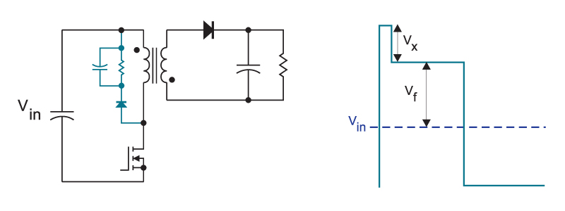