On Sun, 30 Jan 2022 16:15:27 -0500, Ralph Mowery
<
rmowery42@charter.net> wrote:
Very good.
Well, not so good. As usual, I proofread my stuff after I post it. I
should not have included a solder sucker. That's fine for old PCB
boards with fat (1oz) and wide (0.1") traces. However, today's SMD
PCB's use much less copper and narrower traces. Try to suck solder
from a modern board, and the vacuum will suck the copper trace along
with the solder. Best to leave the solder sucker out of the list.
I use some kapton tape instead of the foil to keep the heat
away from other parts. Cover all the close parts and cut a hole where
you want to remove the part. Get some very fine solder of the tin/lead
type and one of the flux despensers that looks like the covid shot
needle. Flux is your friend.
Aluminum foil is cheaper, reflects the heat, bends around corners and
conforms easily to odd shaped areas and parts. I have rolls of the
really fine 0.021 lead/tin solder, but I never seem to use it. I've
settled on Kester 44 rosin core 63/37 in 0.050 and 0.062.
Some of the desoldering braid comes in
handy.
I haven't had much luck using braid for SMD PCB's. Too much danger of overheating and destroying the pads. Braid is useful for connectors
and cleaning up the mess when I use too much solder.
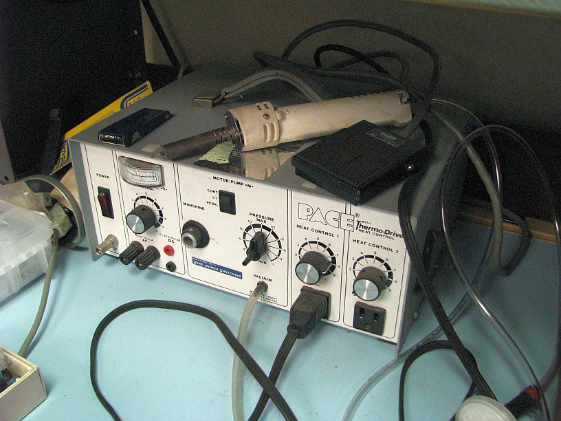
I have one of the hot air stations like you show and it works well for
the hobby.
Old, but reliable: <
http://www.learnbydestroying.com/jeffl/crud/pace-desoldering-station.jpg>
I have two others (but no photos).
<
https://www.ebay.com/itm/353259898775>
and one that was a prototype for a product that never was put in
production. When I closed my office in late 2020, I dragged most
everything home. I also emptied my Subaru, which was acting as a
service "truck". So, I now have two or three of everything.
One other thing that may be a deal breaker is a good stereo microscope.
ONe like this is about the best buy for the money. I most often use the
10x, but I am 72 years old and started the SMD work about 10 years ago.
https://www.amazon.com/AmScope-SE400-Z-Professional-Microscope-Magnification/dp/B005C75IVM
The Amscope se400 for about $ 235.
Without the scope you can plan on spending around $ 100 to $ 150 for all
the things you should need.
I'm 74 years ancient. The hands are still steady but the eyesight is
becoming a problem.
Agreed. I have a small collection of assorted microscopes. <
http://www.learnbydestroying.com/jeffl/pics/microscopes/index.html>
For PCB work, I use an Olympus SZ30: <
http://www.learnbydestroying.com/jeffl/pics/microscopes/Olympus%20SZ30/index.html>
Also, you might need a stand. This one weighs about 40 lbs: <
http://www.learnbydestroying.com/jeffl/pics/microscopes/Olympus%20SZ30/index.html#SZ30-01.jpg>
Look for a microscope that has as much working distance (between the
objective lens and the work piece) as possible. Don't buy a
biological microscope. Biological microscopes have all the fancy
features that you don't need for electronics and all have a tiny
working distances. If you are going to do much soldering under the
microscope, plan on getting a fan to blow away the smoke or cleaning
(or ruining) a few objective lenses including the one's on the turret
that you're NOT using.
You'll also need a ring illuminator. Not having to deal with shadows
is the main benefit. I have one of these: <
https://www.ebay.com/itm/271435251906>
If I buy another one, I'll get one that emits more light or has more
LED's. I also suggest using the microscope mirror light to illuminate
the PCB from below, looking through the PCB. With luck, that will
show broken traces, shorts, solder blobs, cracks etc.
Using a CMOS USB camera to see what I'm doing on a big LCD screen, was
not as wonderful as I expected. It takes some practice to look at a
screen, while soldering under a microscope. I need more practice.
Still, if I were shopping for a microscope, I would get a trinocular.
Be sure get a 0.5x reduction lens with the CMOS camera or the field of
view will be about 1/2 of what's available. Similarly, if you find a
monocular microscope with insufficient working distance, you can
double the distance with a 0.5x Barlow lens.
--
Jeff Liebermann
jeffl@cruzio.com
PO Box 272
http://www.LearnByDestroying.com
Ben Lomond CA 95005-0272
Skype: JeffLiebermann AE6KS 831-336-2558
--- SoupGate-Win32 v1.05
* Origin: fsxNet Usenet Gateway (21:1/5)